GCSE Physics Tutorial: Required Practical 3 - Investigating Factors Affecting the Resistance of Electrical Circuits
In this required practical, we will explore how to set up and check appropriate circuits to investigate two factors affecting the resistance of electrical circuits: the length of a wire at constant temperature and combinations of resistors in series and parallel. Investigating resistance is an essential aspect of understanding the behaviour of electrical components and circuits. Let's get started!
1. Investigating the Effect of Wire Length:
Materials Needed:
Power supply
Ammeter
Voltmeter
Constantan wire (or any suitable wire of different lengths)
Crocodile clips
Ruler
Connecting wires
Procedure:
Set up the circuit.
Cut the constantan wire into different lengths (e.g., 10 cm, 20 cm, 30 cm, 40 cm, and 50 cm). Attach one end of the wire to the positive terminal of the power supply and the other end to the negative terminal using crocodile clips.
Record the length of the wire used and the readings of current (I) from the ammeter and potential difference (V) from the voltmeter.
Calculate the resistance (R) of the wire using Ohm's Law (R = V / I).
Repeat the experiment with each wire length at least three times to ensure accuracy and consistency of results.
Plot a graph of wire length (x-axis) against resistance (y-axis) to observe any patterns.
Analysis:
Analyse the graph to see how the resistance changes with the length of the wire.
You should observe that as the wire length increases, the resistance also increases. This is because the longer the wire, the greater the number of collisions between the free electrons and atoms, resulting in higher resistance.
2. Investigating Combinations of Resistors in Series and Parallel:
Materials Needed:
Power supply
Ammeter
Voltmeter
Resistor (R1)
Resistor (R2)
Crocodile clips
Connecting wires
Procedure:
For the series combination, set up the circuit.
Measure the readings of current (I) from the ammeter and potential difference (V) from the voltmeter.
Calculate the total resistance (R_total) of the series combination using Ohm's Law (R_total = V / I).
For the parallel combination, set up the circuit.
Measure the readings of current (I) from the ammeter and potential difference (V) from the voltmeter.
Calculate the total resistance (R_total) of the parallel combination using Ohm's Law (R_total = V / I).
Compare the total resistance of the series and parallel combinations.
Analysis:
You should observe that the total resistance of resistors in series is equal to the sum of individual resistances (R_total = R1 + R2), while the total resistance of resistors in parallel is less than the smallest individual resistance (1 / R_total = 1 / R1 + 1 / R2).
Safety Precautions:
Always ensure that the power supply voltage is set to a safe and suitable value (low voltage) for the experiment.
Handle wires and resistors carefully to avoid short circuits and accidental electric shocks.
Conclusion: By performing this required practical, you will gain valuable insights into how the resistance of electrical circuits can be affected by factors like wire length and combinations of resistors in series and parallel. This knowledge is essential in understanding the behaviour of electrical components and designing efficient circuits for various applications.
Example data
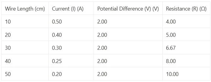
Analysis:
Plotting a graph of wire length (x-axis) against resistance (y-axis) will show a clear trend of increasing resistance with increasing wire length, confirming Ohm's Law.
2. Investigating Combinations of Resistors in Series and Parallel:
Materials Used:
Power supply
Ammeter
Voltmeter
Resistor (R1) with a resistance of 10 Ω
Resistor (R2) with a resistance of 20 Ω
Crocodile clips
Connecting wires
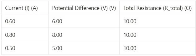
Example Data Table:
Series Combination:

Parallel Combination:
Analysis:
In the series combination, the total resistance is constant at 30 Ω, as expected since the resistors are connected end-to-end.
In the parallel combination, the total resistance is approximately 10 Ω, which is less than the smallest individual resistance (10 Ω and 20 Ω). This is in accordance with the principle that the total resistance in parallel is less than the smallest resistance.
By conducting these experiments and analysing the data, you can gain a deeper understanding of the factors affecting the resistance of electrical circuits and how different components behave when combined in series and parallel configurations. This practical experience helps reinforce the concepts of Ohm's Law and circuit behaviour, which are essential in the study of electricity and electronics.
Looking for a more dynamic learning experience?
Explore our engaging video lessons and interactive animations that GoPhysics has to offer – your gateway to an immersive physics education!