GCSE Physics Tutorial: Understanding Component Properties from Graphs
Graphs are powerful tools that help us visualise and analyse the behaviour of components in electrical circuits. By examining graphs of voltage-current (V-I) characteristics, resistance-temperature, or other relevant relationships, we can gain valuable insights into the properties of components. In this tutorial, we will explore how to interpret graphs to understand the properties of different components.
1. Voltage-Current (V-I) Characteristics:
The V-I graph represents the relationship between voltage (V) and current (I) in a component.
For resistors, the V-I graph is a straight line passing through the origin, indicating that the resistance is constant (Ohmic behaviour). The slope of the line represents the resistance value.
For diodes, the V-I graph shows that current only flows in one direction (forward bias), and there is negligible current flow in the opposite direction (reverse bias). Diodes exhibit non-Ohmic behaviour, meaning their resistance is not constant.
2. Resistance-Temperature Graph:
For thermistors, the resistance-temperature graph is nonlinear, showing that resistance changes with temperature.
NTC (Negative Temperature Coefficient) thermistors have a graph where resistance decreases as temperature increases. PTC (Positive Temperature Coefficient) thermistors exhibit the opposite behaviour, where resistance increases with temperature.
3. Light Intensity-Resistance Graph:
For Light Dependent Resistors (LDRs), the graph shows that resistance decreases as light intensity increases. LDRs exhibit non-Ohmic behaviour.
4. Capacitance-Voltage Graph:
For capacitors, the graph shows the relationship between the voltage across the capacitor and the amount of charge it can store (capacitance).
The graph is a straight line, and the slope represents the capacitance value. The larger the slope, the larger the capacitance.
5. Inductance-Current Graph:
For inductors, the graph shows the relationship between current passing through the inductor and the magnetic flux it generates (inductance).
The graph is typically a straight line, and the slope represents the inductance value. Larger slope indicates higher inductance.
6. Key Points:
Ohmic Behaviour: Components with straight-line V-I graphs have a constant resistance and exhibit Ohmic behaviour (e.g., resistors).
Non-Ohmic Behaviour: Components with nonlinear V-I graphs have varying resistance with voltage or current changes (e.g., diodes, LDRs, thermistors).
Temperature Sensitivity: For thermistors, the steeper the resistance-temperature graph, the higher the sensitivity to temperature changes.
Capacitance: For capacitors, the slope of the capacitance-voltage graph indicates the capacitive storage capacity.
Inductance: For inductors, the slope of the inductance-current graph represents the inductance value, which determines the strength of the magnetic field.
7. Practical Applications:
Understanding component properties from graphs is crucial for selecting appropriate components for specific applications.
Engineers and designers use graphs to predict and analyse the behaviour of circuits under various conditions.
8. Summary: Interpreting graphs of component properties allows us to understand their behaviour and characteristics. By analysing voltage-current (V-I) characteristics, resistance-temperature graphs, and other relevant relationships, we can determine whether components exhibit Ohmic or non-Ohmic behaviour, temperature sensitivity, capacitance, and inductance. This knowledge is essential for designing and analysing circuits effectively, enabling us to select the right components for various electronic applications.
Looking for a more dynamic learning experience?
Explore our engaging video lessons and interactive animations that GoPhysics has to offer – your gateway to an immersive physics education!
GCSE Physics Tutorial: Designing Circuits to Measure Resistance of a Component Using Ammeters and Voltmeters
Measuring the resistance of a component is an essential task in electronics and electrical experiments. To accurately measure resistance, you can design circuits that incorporate ammeters and voltmeters in the correct configuration. In this tutorial, we will guide you through the process of designing such circuits step by step.
1. Components Needed:
The component whose resistance you want to measure (e.g., resistor, thermistor, etc.).
Power supply (e.g., battery or power pack).
Ammeter (measures current in amperes, A).
Voltmeter (measures potential difference in volts, V).
Connecting wires.
2. Circuit Setup: To measure the resistance of the component, we'll use the "Ohm's Law" principle, which states that resistance (R) is equal to the potential difference (V) across the component divided by the current (I) flowing through it (R = V/I).
3. Circuit Design:
Connect the component (whose resistance you want to measure) in series with the ammeter and the power supply. Ensure the positive and negative terminals of the component are correctly aligned with the circuit.
Place the voltmeter across the component in parallel. Connect one end of the voltmeter to one end of the component and the other end of the voltmeter to the other end of the component.
Make sure the ammeter is correctly connected in series with the component to measure the current flowing through it.
Similarly, ensure the voltmeter is correctly connected in parallel with the component to measure the potential difference (voltage) across it.
Adjust the power supply to a suitable and safe voltage, depending on the component's specifications and the ammeter and voltmeter ranges.
Record the current (I) from the ammeter and the potential difference (V) from the voltmeter.
4. Calculating Resistance: Use Ohm's Law (R = V/I) to calculate the resistance (R) of the component. Substitute the values of the measured current (I) and potential difference (V) into the formula to determine the resistance.
5. Safety Precautions:
Ensure the power supply voltage is set to a safe and suitable level (low voltage) for the experiment.
Handle components and wires carefully to avoid short circuits and accidental electric shocks.
6. Summary: Designing circuits to measure the resistance of a component involves connecting the component in series with an ammeter and a power supply, as well as placing a voltmeter in parallel across the component. This configuration allows you to measure the current and potential difference, enabling you to calculate the resistance using Ohm's Law (R = V/I). By following these steps and safety precautions, you can accurately measure the resistance of various components, helping you analyse and understand their electrical characteristics.
Looking for a more dynamic learning experience?
Explore our engaging video lessons and interactive animations that GoPhysics has to offer – your gateway to an immersive physics education!
GCSE Physics Tutorial: Examples of Using an LDR in Circuits
Light Dependent Resistors (LDRs) are versatile components used in electronic circuits to detect changes in light intensity. Their ability to change resistance based on light levels makes them valuable for various light sensing and control applications. In this tutorial, we will explore practical examples of using an LDR in circuits, with a focus on switching lights on when it gets dark.
1. Automatic Light Control: Switching Lights On When It Gets Dark
How It Works:
The LDR is connected in series with a lamp (light) and a relay or switch.
In bright light conditions, the LDR exhibits low resistance, allowing current to flow through it.
The low resistance of the LDR keeps the relay or switch in the "off" position, preventing the lamp from lighting up.
As the ambient light decreases (e.g., at dusk or night), the resistance of the LDR increases due to reduced light intensity.
The higher resistance of the LDR activates the relay or switch, completing the circuit and allowing current to flow through the lamp, thereby switching the light on.
As the ambient light increases again (e.g., during daylight), the resistance of the LDR decreases, turning the relay or switch "off" and turning the lamp off.
Practical Applications:
This circuit is commonly used in outdoor lighting, street lamps, and garden lights to automatically switch on the lights at night and turn them off during the day.
It can also be employed in indoor applications, such as automatic night lights and light-sensitive switchboards.
2. Burglar Deterrent: Turning Lights On in Response to Movement
How It Works:
The LDR is connected in series with a lamp (light) and a relay or switch.
During the day or in bright light conditions, the LDR's low resistance keeps the relay or switch in the "off" position, and the lamp remains off.
At night or in low-light conditions, the LDR's resistance increases due to reduced light intensity.
Additionally, a passive infrared (PIR) sensor or a motion sensor is used in the circuit to detect any movement or change in infrared radiation.
When the PIR sensor detects movement or a change in infrared radiation, it activates the relay or switch, completing the circuit and turning the lamp on.
After a set period of inactivity or when the light intensity increases (e.g., during daylight), the relay or switch is deactivated, turning the lamp off.
Practical Applications:
This circuit is useful as a security measure in homes and commercial buildings. When an intruder is detected, the lights are turned on, discouraging unwanted activities and enhancing security.
Summary: Light Dependent Resistors (LDRs) are invaluable components in circuits that respond to changes in light intensity. They are used in various light sensing and control applications, including automatically switching lights on when it gets dark. By employing LDRs in these circuits, we can create energy-efficient and convenient systems that respond to changes in ambient light levels, providing increased safety and convenience in various scenarios.
Looking for a more dynamic learning experience?
Explore our engaging video lessons and interactive animations that GoPhysics has to offer – your gateway to an immersive physics education!
GCSE Physics Tutorial: Relationship between Light Intensity and LDR Resistance
Light Dependent Resistors (LDRs) are semiconductor devices that exhibit changes in resistance in response to variations in light intensity. Understanding the relationship between light intensity and LDR resistance is essential for using LDRs in light sensing and control applications. In this tutorial, we will explore the characteristics of LDRs and the effect of light intensity on their resistance.
1. What is an LDR?
A Light Dependent Resistor (LDR), also known as a photoresistor, is a passive electronic component made of semiconductor materials that respond to light.
LDRs are specifically designed to be light-sensitive, and they can detect changes in the amount of incident light.
2. Light Intensity and LDR Resistance Relationship:
The resistance of an LDR decreases as the intensity of incident light increases.
This relationship can be described as follows: More light intensity leads to lower resistance and less light intensity results in higher resistance.
3. How It Works:
An LDR consists of a semiconductor material that has a high resistance in the dark or low-light conditions.
When light falls on the surface of the LDR, photons in the incident light excite electrons in the semiconductor material.
As a result, more charge carriers (electrons) become available, reducing the resistance of the LDR.
The lower resistance allows more current to flow through the LDR in response to increased light intensity.
4. Practical Applications:
LDRs are commonly used in light sensing applications, such as:
Light-sensitive street lamps: LDRs can detect the ambient light level and automatically adjust the brightness of street lamps accordingly.
Camera exposure control: In photography, LDRs can help in controlling the camera's exposure settings based on the available light.
Security systems: LDRs can be used in security systems to detect changes in light intensity, such as someone entering a room or area.
5. Safety Precautions:
Handle LDRs and other electronic components with care to avoid damage.
When applying voltage or current to an LDR, ensure that the power supply is set to safe and suitable levels.
6. Summary: LDRs exhibit a change in resistance based on the intensity of incident light. As the light intensity increases, the resistance of an LDR decreases, allowing more current to flow through it. This characteristic makes LDRs valuable components in light sensing and control applications, enabling devices and systems to respond to changes in ambient light levels efficiently.
By understanding the relationship between light intensity and LDR resistance, you can apply LDRs effectively in various electronic circuits, contributing to energy-efficient and smart applications in photography, lighting, security, and more.
Looking for a more dynamic learning experience?
Explore our engaging video lessons and interactive animations that GoPhysics has to offer – your gateway to an immersive physics education!
GCSE Physics Tutorial: Examples of Using a Thermistor in a Circuit
Thermistors, with their temperature-sensitive resistance characteristics, are valuable components in various electronic circuits. They find extensive application in temperature sensing and control systems. In this tutorial, we will explore examples of using a thermistor in a circuit, focusing on a thermostat and other practical applications.
1. Thermostat: A thermostat is a device used to regulate and maintain a specific temperature in a system. It consists of a thermistor as a temperature sensor and a control circuit that adjusts the heating or cooling system to achieve the desired temperature.
How It Works:
As the temperature changes, the thermistor's resistance varies accordingly. When the temperature rises, the thermistor's resistance decreases, and when the temperature falls, the resistance increases.
The thermistor is connected to a control circuit, which measures its resistance and compares it to a reference value corresponding to the desired temperature.
If the temperature is below the desired value, the control circuit activates the heating system (e.g., furnace) to increase the temperature until the desired level is reached.
Conversely, if the temperature is above the desired value, the control circuit activates the cooling system (e.g., air conditioner) to lower the temperature until the desired level is achieved.
By continuously monitoring the thermistor's resistance, the thermostat maintains the desired temperature by regulating the heating or cooling system.
2. Temperature-Controlled Fan: Another practical example is a temperature-controlled fan circuit. This circuit activates a fan to cool down a system when the temperature exceeds a set threshold.
How It Works:
Similar to the thermostat circuit, the thermistor's resistance changes with temperature.
When the temperature rises above the set threshold, the thermistor's resistance decreases.
The control circuit detects this change and activates a relay or switch, turning on the cooling fan to dissipate heat and lower the temperature.
As the temperature decreases and the thermistor's resistance increases, the control circuit deactivates the fan.
3. Temperature Alarm: Thermistors are also used in temperature alarm circuits, which trigger an alert when the temperature exceeds a specific limit.
How It Works:
The thermistor continuously senses the temperature of the environment.
If the temperature exceeds the preset limit, the thermistor's resistance changes, activating the control circuit.
The control circuit triggers the alarm, alerting users to the high temperature.
Summary: Thermistors are versatile components used in various circuits, with the thermostat being a prominent application. They provide a cost-effective and accurate way to sense and control temperature, making them essential in temperature-regulated systems, environmental monitoring, and safety applications. These examples illustrate how thermistors play a crucial role in ensuring temperature stability and safeguarding electronic devices and systems.
Looking for a more dynamic learning experience?
Explore our engaging video lessons and interactive animations that GoPhysics has to offer – your gateway to an immersive physics education!
GCSE Physics Tutorial: Relationship of a Thermistor's Resistance with Temperature
A thermistor is a type of temperature-sensitive resistor that exhibits changes in resistance with variations in temperature. Understanding the relationship between a thermistor's resistance and temperature is crucial for various applications, including temperature measurement and control in electronic circuits. In this tutorial, we will explore the characteristics of a thermistor and the mathematical relationship that describes its resistance-temperature behaviour.
1. What is a Thermistor?
A thermistor is a semiconductor device made from metal oxides, such as manganese, nickel, or cobalt. These materials possess temperature-dependent electrical properties, which make thermistors highly sensitive to changes in temperature.
Thermistors come in two types: Positive Temperature Coefficient (PTC) and Negative Temperature Coefficient (NTC). In this tutorial, we will focus on NTC thermistors, which exhibit a decrease in resistance as temperature increases.
2. Resistance-Temperature Relationship:
NTC thermistors follow an exponential relationship between their resistance (R) and temperature (T). This relationship can be expressed mathematically as:
R = R₀ * e^(β * (1/T - 1/T₀))
where:
R: The resistance of the thermistor at temperature T (measured in ohms, Ω).R₀: The resistance of the thermistor at a reference temperature T₀ (usually specified at 25°C).β: The material constant (in Kelvin, K) that characterises the thermistor's temperature sensitivity. It determines the rate of change of resistance with temperature.T: The absolute temperature of the thermistor in Kelvin (K).
3. Key Points:
As the temperature increases, the resistance of an NTC thermistor decreases exponentially. Conversely, as the temperature decreases, the resistance increases.
The resistance-temperature relationship of a thermistor is nonlinear, unlike the linear behaviour of standard resistors.
The material constant
βis specific to each thermistor and is provided by the manufacturer. It is essential for accurately predicting the thermistor's resistance at different temperatures.
4. Practical Applications:
NTC thermistors are widely used in temperature sensing and control applications. For example:
Temperature sensors in thermostats, weather stations, and temperature-controlled systems.
Over-temperature protection in electronic devices to prevent damage due to excessive heat.
Temperature compensation in circuits to ensure accurate performance of components over a range of temperatures.
5. Safety Precautions:
Handle thermistors and other electronic components with care to avoid damage.
When applying a voltage or current to a thermistor, ensure that the power supply is set to safe and suitable levels.
6. Summary: The resistance of an NTC thermistor decreases exponentially as the temperature increases. This nonlinear relationship is a key characteristic of thermistors, allowing them to be highly sensitive temperature sensors used in a wide range of electronic applications.
By understanding the resistance-temperature relationship of thermistors, you can design and implement accurate temperature sensing and control systems. NTC thermistors offer a practical and reliable solution for temperature-related tasks, making them valuable components in various electronic devices and systems.
Looking for a more dynamic learning experience?
Explore our engaging video lessons and interactive animations that GoPhysics has to offer – your gateway to an immersive physics education!
Required Practical 4: Investigating Current and Potential Difference Across Components
In this practical, you will investigate the behaviour of different components, specifically a filament bulb, an ohmic resistor, and a diode. You will compare their resistance and how it changes as the current through them changes.
Equipment Needed:
Power supply
Ammeter
Voltmeter
Filament bulb
Ohmic resistor
Diode
Connecting wires
Procedure:
Set up the circuit.
Start by connecting only the filament bulb to the circuit. Make sure the power supply is turned off.
Turn on the power supply and note down the ammeter reading (current) and voltmeter reading (voltage) across the filament bulb.
Turn off the power supply and disconnect the filament bulb.
Repeat steps 2-4 for the ohmic resistor and the diode separately.
Observations and Analysis:
Filament Bulb:
As you gradually increase the voltage (and therefore the current) across the filament bulb, you will observe that the brightness of the bulb increases steadily.
The resistance of the filament bulb increases as the current through it increases. This is evident from the fact that the ammeter reading increases while the voltmeter reading also increases, but not proportionally.
Ohmic Resistor:
The ohmic resistor will show a linear relationship between voltage and current. This means that as you increase the voltage, the current increases proportionally.
The resistance of an ohmic resistor remains constant, regardless of the current passing through it. This is why the ammeter and voltmeter readings will change in a linear fashion.
Diode:
The diode behaves differently from the other components. When connected in the correct orientation, it will allow current to flow only in one direction (forward bias), and you will observe a relatively low resistance.
When you reverse the direction of the diode (reverse bias), it will behave like an open circuit, allowing very little current to pass through it. The resistance in this direction is significantly high.
Conclusion:
The filament bulb shows non-linear behaviour, with its resistance increasing as the current increases.
The ohmic resistor demonstrates linear behaviour, maintaining a constant resistance as the current changes.
The diode behaves as a one-way conductor, with low resistance in one direction (forward bias) and high resistance in the other direction (reverse bias).
This practical experiment highlights the differences in behaviour among different components and helps you understand how their resistance changes with varying current. It also provides insights into the fundamental concepts of resistance and the characteristics of different electrical components.
Looking for a more dynamic learning experience?
Explore our engaging video lessons and interactive animations that GoPhysics has to offer – your gateway to an immersive physics education!
GCSE Physics Tutorial: Required Practical 3 - Investigating Factors Affecting the Resistance of Electrical Circuits
In this required practical, we will explore how to set up and check appropriate circuits to investigate two factors affecting the resistance of electrical circuits: the length of a wire at constant temperature and combinations of resistors in series and parallel. Investigating resistance is an essential aspect of understanding the behaviour of electrical components and circuits. Let's get started!
1. Investigating the Effect of Wire Length:
Materials Needed:
Power supply
Ammeter
Voltmeter
Constantan wire (or any suitable wire of different lengths)
Crocodile clips
Ruler
Connecting wires
Procedure:
Set up the circuit.
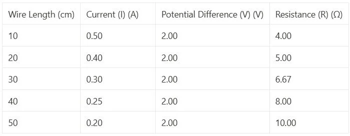
Cut the constantan wire into different lengths (e.g., 10 cm, 20 cm, 30 cm, 40 cm, and 50 cm). Attach one end of the wire to the positive terminal of the power supply and the other end to the negative terminal using crocodile clips.
Record the length of the wire used and the readings of current (I) from the ammeter and potential difference (V) from the voltmeter.
Calculate the resistance (R) of the wire using Ohm's Law (R = V / I).
Repeat the experiment with each wire length at least three times to ensure accuracy and consistency of results.
Plot a graph of wire length (x-axis) against resistance (y-axis) to observe any patterns.
Analysis:
Analyse the graph to see how the resistance changes with the length of the wire.
You should observe that as the wire length increases, the resistance also increases. This is because the longer the wire, the greater the number of collisions between the free electrons and atoms, resulting in higher resistance.
2. Investigating Combinations of Resistors in Series and Parallel:
Materials Needed:
Power supply
Ammeter
Voltmeter
Resistor (R1)
Resistor (R2)
Crocodile clips
Connecting wires
Procedure:
For the series combination, set up the circuit.
Measure the readings of current (I) from the ammeter and potential difference (V) from the voltmeter.
Calculate the total resistance (R_total) of the series combination using Ohm's Law (R_total = V / I).
For the parallel combination, set up the circuit.
Measure the readings of current (I) from the ammeter and potential difference (V) from the voltmeter.
Calculate the total resistance (R_total) of the parallel combination using Ohm's Law (R_total = V / I).
Compare the total resistance of the series and parallel combinations.
Analysis:
You should observe that the total resistance of resistors in series is equal to the sum of individual resistances (R_total = R1 + R2), while the total resistance of resistors in parallel is less than the smallest individual resistance (1 / R_total = 1 / R1 + 1 / R2).
Safety Precautions:
Always ensure that the power supply voltage is set to a safe and suitable value (low voltage) for the experiment.
Handle wires and resistors carefully to avoid short circuits and accidental electric shocks.
Conclusion: By performing this required practical, you will gain valuable insights into how the resistance of electrical circuits can be affected by factors like wire length and combinations of resistors in series and parallel. This knowledge is essential in understanding the behaviour of electrical components and designing efficient circuits for various applications.
Example data
Analysis:
Plotting a graph of wire length (x-axis) against resistance (y-axis) will show a clear trend of increasing resistance with increasing wire length, confirming Ohm's Law.
2. Investigating Combinations of Resistors in Series and Parallel:
Materials Used:
Power supply
Ammeter
Voltmeter
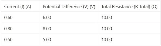
Resistor (R1) with a resistance of 10 Ω
Resistor (R2) with a resistance of 20 Ω
Crocodile clips
Connecting wires
Example Data Table:
Series Combination:

Parallel Combination:
Analysis:
In the series combination, the total resistance is constant at 30 Ω, as expected since the resistors are connected end-to-end.
In the parallel combination, the total resistance is approximately 10 Ω, which is less than the smallest individual resistance (10 Ω and 20 Ω). This is in accordance with the principle that the total resistance in parallel is less than the smallest resistance.
By conducting these experiments and analysing the data, you can gain a deeper understanding of the factors affecting the resistance of electrical circuits and how different components behave when combined in series and parallel configurations. This practical experience helps reinforce the concepts of Ohm's Law and circuit behaviour, which are essential in the study of electricity and electronics.
Looking for a more dynamic learning experience?
Explore our engaging video lessons and interactive animations that GoPhysics has to offer – your gateway to an immersive physics education!
GCSE Physics Tutorial: Ohm's Law Equation
Ohm's Law is a fundamental principle in electrical circuits that describes the relationship between voltage (potential difference), current, and resistance. It provides a simple and powerful equation to calculate one of these parameters when the other two are known. In this tutorial, we will explore Ohm's Law and its equation.
1. Ohm's Law: Ohm's Law states that the current flowing through a conductor is directly proportional to the voltage (potential difference) across the conductor and inversely proportional to the resistance of the conductor. Mathematically, Ohm's Law can be expressed as follows:
V = I × R
where:
V: Represents the potential difference (voltage) across the conductor, measured in volts (V).
I: Denotes the current flowing through the conductor, measured in amperes (A).
R: Signifies the resistance of the conductor, measured in ohms (Ω).
2. Understanding the Equation:
The equation V = I × R indicates that the voltage across a conductor is equal to the current flowing through the conductor multiplied by its resistance.
If the voltage (V) across the conductor increases while the resistance (R) remains constant, the current (I) flowing through the conductor will also increase.
Similarly, if the voltage (V) across the conductor remains constant and the resistance (R) increases, the current (I) flowing through the conductor will decrease.
3. Practical Applications: Ohm's Law is extensively used in electrical engineering and electronics for circuit analysis, design, and troubleshooting.
It allows engineers to calculate the voltage, current, or resistance in a circuit when the other two values are known.
Ohm's Law is particularly valuable when working with resistors, conductors, and semiconductor devices, enabling engineers to predict and control the behaviour of components.
4. Units:
Voltage is measured in volts (V).
Current is measured in amperes (A).
Resistance is measured in ohms (Ω).
5. Summary:
Ohm's Law states that voltage (V) is equal to the current (I) multiplied by the resistance (R) in an electrical circuit.
The equation V = I × R is a powerful tool for calculating and understanding the behaviour of electrical components and circuits.
Ohm's Law is widely used in electrical engineering to analyse and design circuits, making it a fundamental principle in the study of electricity.
By understanding Ohm's Law and its equation, you can make informed decisions when working with electrical circuits and components. It provides a valuable tool for predicting and controlling current, voltage, and resistance in various electrical systems, allowing for efficient and safe design and operation of electronic devices and systems.
Looking for a more dynamic learning experience?
Explore our engaging video lessons and interactive animations that GoPhysics has to offer – your gateway to an immersive physics education!
GCSE Physics Tutorial: Understanding the Difference between Voltage and Potential Difference
In physics and electrical circuits, voltage and potential difference are related concepts, but they have distinct meanings and contexts. Understanding the difference between these terms is essential for accurately describing electrical phenomena and analysing circuits. In this tutorial, we will explore the key differences between voltage and potential difference.
1. Voltage:
Definition: Voltage is a measure of the electrical potential energy difference between two points in an electrical circuit. It represents the energy supplied or required to move a unit of electric charge from one point to another.
Symbol: The symbol for voltage is "V."
Units: Voltage is measured in volts (V) in the International System of Units (SI).
2. Potential Difference:
Definition: Potential difference is synonymous with voltage and represents the difference in electrical potential energy between two points in an electrical circuit. It signifies the change in electrical potential energy per unit of electric charge as it moves from one point to another.
Symbol: The symbol for potential difference is also "V."
Units: Like voltage, potential difference is measured in volts (V).
3. Key Difference: The main difference between voltage and potential difference is in the way the terms are used and interpreted in different contexts.
Voltage: Voltage is often used in a general sense when discussing electricity and electrical circuits. It describes the potential energy difference between two points, which can be across a component, a circuit, or a power source. For example, when we talk about the voltage of a battery, we refer to the potential energy difference between its positive and negative terminals.
Potential Difference: Potential difference is a more specific term used to describe the voltage between two points within a circuit or a component. It focuses on the energy difference experienced by electric charges as they move from one point to another. When we mention potential difference across a resistor or a capacitor, we refer to the specific energy difference experienced by the charges passing through that component.
4. Practical Application: Understanding the difference between voltage and potential difference is essential for analysing electrical circuits and calculating circuit parameters. By using the concept of potential difference, engineers and scientists can determine the energy changes experienced by electric charges as they move through various components in a circuit.
5. Summary:
Voltage and potential difference are related concepts, both representing the electrical potential energy difference between two points.
Voltage is a general term used to describe potential energy differences in electrical systems, while potential difference is more specific, focusing on energy changes between two points within a circuit or component.
By having a clear idea of the distinction between voltage and potential difference, you can communicate effectively when describing electrical phenomena and analysing electrical circuits. Both terms play significant roles in electrical engineering and are vital for understanding how electricity behaves in various applications.
Looking for a more dynamic learning experience?
Explore our engaging video lessons and interactive animations that GoPhysics has to offer – your gateway to an immersive physics education!
GCSE Physics Tutorial: Relation between Current, Resistance, and Potential Difference
In electrical circuits, the relationship between current, resistance, and potential difference (voltage) is governed by Ohm's Law. Understanding this relationship is fundamental for analysing and predicting the behaviour of electrical components in various circuits. In this tutorial, we will recall Ohm's Law and explore how current is dependent on both the resistance of a component and the potential difference across it.
1. Ohm's Law:
Ohm's Law is a fundamental principle in electricity that describes the relationship between current, resistance, and potential difference. It is expressed mathematically as:
V = I × R
where: V = Potential Difference (Voltage) across the component (in volts, V) I = Current flowing through the component (in amperes, A) R = Resistance of the component (in ohms, Ω)
2. Understanding Ohm's Law:
Ohm's Law states that the potential difference (voltage) across a component is directly proportional to the current flowing through it and the resistance of the component.
The potential difference (V) is the driving force that causes electric charges to move through a circuit. It represents the electrical energy provided to each coulomb of charge flowing through the component.
The current (I) is the rate at which electric charge flows through the component. It is a measure of the amount of charge passing a point in the circuit per second.
The resistance (R) represents the opposition encountered by the current as it flows through the component. It quantifies how much the component resists the flow of charge.
3. Dependency of Current on Resistance and Potential Difference:
Current is dependent on both the resistance of a component and the potential difference across it. According to Ohm's Law, the current flowing through a component is directly proportional to the potential difference and inversely proportional to the resistance. This can be expressed as:
I ∝ V / R
If the potential difference (V) across a component increases while the resistance (R) remains constant, the current (I) through the component will also increase.
Similarly, if the potential difference (V) remains constant and the resistance (R) increases, the current (I) through the component will decrease.
4. Practical Applications:
Ohm's Law is widely used in electrical engineering and electronics for circuit analysis and design. It enables engineers to calculate and predict current, voltage, and resistance in various circuits.
Ohm's Law is crucial for understanding how different components, such as resistors, conductors, and semiconductor devices, behave in electrical circuits.
Summary:
Ohm's Law (V = I × R) describes the relationship between current (I), resistance (R), and potential difference (V) in an electrical circuit.
Current is directly proportional to the potential difference and inversely proportional to the resistance according to Ohm's Law.
Understanding Ohm's Law is essential for predicting the behaviour of electrical components and analysing various electrical circuits.
By recalling Ohm's Law and understanding the relationship between current, resistance, and potential difference, you can gain valuable insights into the behaviour of electrical circuits and make informed decisions when designing, analysing, and troubleshooting various electrical systems. Ohm's Law is a foundational concept in the study of electricity and plays a key role in modern technology and engineering.
Looking for a more dynamic learning experience?
Explore our engaging video lessons and interactive animations that GoPhysics has to offer – your gateway to an immersive physics education!
GCSE Physics Tutorial: Current is the Same at Any Point in a Single Closed Loop
In electrical circuits, the flow of electric charge, known as current, follows specific rules and principles. One fundamental principle is that the current is the same at any point in a single closed loop. Understanding this concept is crucial for analyzing and troubleshooting electrical circuits. In this tutorial, we will explore the significance of current being constant within a single closed loop.
1. Closed Loop:
A closed loop is a continuous pathway through which electric charges can flow. It forms a complete circuit, allowing the current to circulate from the power source through various components and back to the power source. A closed loop ensures the continuity of the electric circuit, enabling the flow of charges.
2. Conservation of Charge:
The principle of conservation of charge states that electric charge cannot be created or destroyed. In an electric circuit, the total amount of charge entering a closed loop must be equal to the total amount of charge leaving the loop. This principle ensures that the flow of electric charge remains constant within a single closed loop.
3. Kirchhoff's Current Law (KCL):
Kirchhoff's Current Law, also known as the junction rule, is a fundamental law in electrical circuit analysis. It states that the total current entering a junction (or node) in an electrical circuit is equal to the total current leaving the junction. Mathematically, this can be represented as:
$$Σ I_{in} = Σ I_{out}$$
where: $Σ I_{in}$ = Sum of currents entering the junction $Σ I_{out}$ = Sum of currents leaving the junction
4. Current in Series and Parallel Circuits:
In a series circuit, where components are connected in a single closed loop, the current is the same at any point in the circuit. This is because there is only one path for the current to flow.
In a parallel circuit, where components are connected in multiple closed loops, the current may vary at different points in the circuit. However, the total current entering a junction must be equal to the total current leaving the junction, as stated by Kirchhoff's Current Law.
5. Application in Circuit Analysis:
The principle that current is the same at any point in a single closed loop is valuable in analyzing and solving electrical circuits. By knowing the current at one point in the loop, you can determine the current at any other point within the same loop.
This principle also aids in identifying the relationship between currents and resistances in series and parallel circuits, making it essential for designing and understanding complex electrical systems.
Summary:
Current is constant at any point within a single closed loop in an electrical circuit.
Kirchhoff's Current Law states that the total current entering a junction must be equal to the total current leaving the junction.
Understanding this principle is essential for circuit analysis, troubleshooting, and designing electrical circuits.
By grasping the concept that current is the same at any point in a single closed loop, you can gain insights into the behavior of electrical circuits and confidently apply Kirchhoff's laws to analyze and solve complex circuit problems.
Looking for a more dynamic learning experience?
Explore our engaging video lessons and interactive animations that GoPhysics has to offer – your gateway to an immersive physics education!
GCSE Physics Tutorial: Units for Current, Charge, and Time
In physics, understanding and using the correct units for various quantities are crucial for accurate measurements and calculations. In this tutorial, we will recall the units for current, electric charge, and time, which are essential concepts when working with electricity.
1. Current (I):
Unit: The unit for electric current is the ampere (A).
Symbol: The symbol for ampere is "A".
Definition: One ampere (1 A) of current represents the flow of one coulomb of electric charge per second through a conductor.
2. Electric Charge (Q):
Unit: The unit for electric charge is the coulomb (C).
Symbol: The symbol for coulomb is "C".
Definition: One coulomb (1 C) of electric charge is equivalent to approximately 6.24 x 10^18 elementary charges (e) or the charge of one mole of electrons.
3. Time (t):
Unit: The unit for time is the second (s).
Symbol: The symbol for second is "s".
Definition: One second (1 s) is the base unit of time in the International System of Units (SI). It is defined as the duration of 9,192,631,770 periods of the radiation corresponding to the transition between two hyperfine levels of the ground state of the cesium-133 atom.
Summary:
Current is measured in amperes (A).
Electric charge is measured in coulombs (C).
Time is measured in seconds (s).
Practical Applications:
When working with electrical circuits, you use amperes to measure the current flowing through the circuit using an ammeter.
Coulombs are used to quantify the amount of electric charge that has passed through a component or a circuit during a specific time period.
Seconds are commonly used to measure the time taken for various electrical processes, such as the charging or discharging of a capacitor or the duration of an electrical event.
Important Note:
When performing calculations, ensure that the units for current, electric charge, and time are consistent. Always pay attention to the units and conversions to obtain accurate results.
In some situations, milliamperes (mA) and microamperes (μA) may also be used to measure small currents, where 1 mA is equal to 0.001 A, and 1 μA is equal to 0.000001 A.
Understanding and using the correct units is fundamental in physics, and it allows scientists and engineers to communicate effectively, conduct experiments, and make accurate measurements in various scientific and engineering fields, including electricity and electronics.
Looking for a more dynamic learning experience?
Explore our engaging video lessons and interactive animations that GoPhysics has to offer – your gateway to an immersive physics education!
GCSE Physics Tutorial: Applying the Equation for Current Flow
In the previous tutorial, we learned about the definition of current and the mathematical relationship between current (I), electric charge (Q), and time (t). In this tutorial, we will explore how to apply the equation for current flow in practical scenarios involving electrical circuits.
1. Equation for Current Flow: The equation for current flow is given by:
I = Q / twhere: I = Current (in amperes, A) Q = Electric charge (in coulombs, C) t = Time (in seconds, s)
2. Example 1: Calculating Current: Let's apply the equation to a simple scenario. Suppose a circuit carries an electric charge of 200 coulombs in 10 seconds. To find the current flowing in the circuit, we can use the equation:
I = Q / t
I = 200 C / 10 s
I = 20 A
The current flowing in the circuit is 20 amperes.
3. Example 2: Calculating Charge: Conversely, if we know the current and the time, we can calculate the electric charge. For instance, if a circuit has a current of 5 amperes flowing through it for 15 seconds, we can determine the charge using the same equation:
I = Q / t
5 A = Q / 15 s
Q = 5 A x 15 s
Q = 75 C
The electric charge in the circuit is 75 coulombs.
4. Real-World Application: Battery Charging The equation for current flow is commonly used in scenarios involving battery charging. When charging a battery, the charging current (I) and the time (t) are essential parameters. By measuring the current and knowing the charging time, one can calculate the amount of charge supplied to the battery during the charging process.
5. Using an Ammeter: To apply the current equation practically, you need to measure the current in a circuit. This is done using an ammeter, a device specifically designed to measure electric current. An ammeter should be connected in series with the component or the circuit you want to measure the current flowing through.
6. Units: Ensure that the units for current (I), electric charge (Q), and time (t) are consistent. For example, use amperes (A) for current, coulombs (C) for charge, and seconds (s) for time.
7. Summary: The equation for current flow (I = Q / t) is a fundamental tool in understanding and analysing electrical circuits. It allows us to calculate the current flowing in a circuit or the electric charge carried by the current over a given time. Applying this equation enables us to make informed decisions in designing and troubleshooting electrical systems, making it a crucial aspect of working with electricity.
Note: Be cautious and ensure safety while working with electricity. Always disconnect the circuit before measuring or making changes to avoid electric shock or damage to equipment.
Looking for a more dynamic learning experience?
Explore our engaging video lessons and interactive animations that GoPhysics has to offer – your gateway to an immersive physics education!
GCSE Physics Tutorial: Definition of Current
Current is a fundamental concept in electricity and is a measure of the flow of electric charge through a conducting medium. Understanding current is essential for comprehending the behaviour of electrical circuits and how electricity is utilised in various applications. In this tutorial, we will define current and explore its key aspects.
1. Definition of Current:
Current (I): Current is the rate of flow of electric charge through a conductor. It is measured in amperes (A), where 1 ampere is defined as the flow of 1 coulomb of charge per second.
2. Electric Charge (Q):
Electric Charge: Electric charge is a fundamental property of matter that can be positive or negative. The elementary unit of electric charge is the charge of an electron, which is approximately -1.6 x 10^-19 coulombs (C).
Coulomb (C): The coulomb is the SI unit of electric charge. It represents the quantity of charge when 1 ampere of current flows for 1 second. One coulomb is equal to the charge of approximately 6.24 x 10^18 electrons.
3. Mathematical Relationship: The relationship between current (I), electric charge (Q), and time (t) can be expressed using the following formula:
I=Qt
where: I = Current (in amperes, A) Q = Electric charge (in coulombs, C) t = Time (in seconds, s)
4. Direction of Current:
Current is defined as the flow of positive charge carriers. In most conductors, such as metals, the charge carriers are electrons, which have a negative charge. Therefore, the direction of current flow is opposite to the movement of electrons. This convention, known as conventional current flow, assumes that current moves from the positive to the negative terminal of a circuit.
5. Measuring Current:
Current is measured using a device called an ammeter. An ammeter is connected in series with the circuit, allowing it to measure the current flowing through a specific component or the entire circuit.
6. Units of Current:
The SI unit of current is the ampere (A). Smaller currents are often measured in milliamperes (mA), where 1 mA is equal to 0.001 amperes. Larger currents may be expressed in kiloamperes (kA), where 1 kA is equal to 1000 amperes.
Conclusion: Current is the flow of electric charge through a conductor and is measured in amperes. It represents the rate at which electric charge moves, and it plays a central role in understanding electrical circuits and the behaviour of electrical systems. By grasping the concept of current, you can gain insight into how electricity is used, transmitted, and controlled in various applications, making it a fundamental aspect of studying physics and electrical engineering.
Looking for a more dynamic learning experience?
Explore our engaging video lessons and interactive animations that GoPhysics has to offer – your gateway to an immersive physics education!
GCSE Physics Tutorial: Requirements for Electrical Charge Flow
Electric charge flow is the movement of electric charges through a conducting material in response to an electric potential difference (voltage). Understanding the requirements for electrical charge flow is essential for comprehending how electricity works and how current is established in a circuit. In this tutorial, we will define the requirements for electrical charge flow.
1. Electric Potential Difference (Voltage):
Definition: Electric potential difference, commonly known as voltage, is the driving force that pushes electric charges to move in a circuit. It is measured in volts (V).
Requirement: To establish charge flow, there must be a difference in electric potential between two points in a circuit. The potential difference creates an electric field that exerts a force on the electric charges, causing them to move from areas of higher potential to areas of lower potential.
2. Conducting Medium:
Definition: A conducting medium is a material that allows the free movement of electric charges, also known as charge carriers. Metals, such as copper and aluminum, are excellent conductors of electricity due to their abundance of free electrons that can move easily within the material.
Requirement: For charge flow to occur, there must be a conducting medium that enables the movement of electric charges through it. Insulators, on the other hand, do not allow charge flow as their electrons are tightly bound and cannot move freely.
3. Closed Circuit:
Definition: A closed circuit is a complete pathway for electric charges to flow from a power source through various components and back to the power source.
Requirement: To sustain charge flow, the circuit must be closed and continuous, allowing a loop for the charges to follow. If there is an interruption or an open circuit, charge flow will cease, and no current will be established.
4. Electric Field:
Definition: An electric field is a region around a charged object or between charged objects where electric forces are exerted on other charged particles.
Requirement: An electric field is necessary to establish charge flow. When a potential difference exists between two points in a circuit, it creates an electric field that exerts a force on the electric charges, propelling them through the conducting medium.
5. Driving Force (EMF - Electromotive Force):
Definition: Electromotive force (EMF) is a term often used to describe the energy supplied by a power source, such as a battery or generator, to drive electric charges in a circuit.
Requirement: The presence of an EMF is necessary to maintain a continuous flow of electric charges in the circuit. It provides the energy needed to push the charges against resistance and maintain a steady current.
6. Charge Carriers:
Definition: Charge carriers are mobile electric charges within a conducting medium. In most conductors, electrons act as charge carriers, while in some cases, positively charged ions may also act as charge carriers.
Requirement: For charge flow to occur, there must be charge carriers present in the conducting medium. The electric field causes these charge carriers to move and create an electric current.
Conclusion: Electrical charge flow requires several key elements to be present and interact within a circuit. These include a potential difference (voltage), a conducting medium, a closed circuit pathway, an electric field, a driving force (EMF), and charge carriers. Understanding these requirements is fundamental to grasping the principles of electricity and how electric current is established and flows in electrical circuits.
Looking for a more dynamic learning experience?
Explore our engaging video lessons and interactive animations that GoPhysics has to offer – your gateway to an immersive physics education!
GCSE Physics Tutorial: Explaining Additional Components in Electrical Circuits
In this tutorial, we will explore additional components that you may encounter in electrical circuits, such as motors, buzzers, heaters, and more. While these components may not have been covered in previous examples, we will explain their purpose in the context of the question.
1. Motor:
Purpose: A motor is an electromechanical device that converts electrical energy into mechanical energy. When current flows through the motor, it generates a magnetic field that interacts with the magnetic field of the motor's coils, causing the motor shaft to rotate. This rotational motion can be used to drive various mechanical systems, such as fans, wheels, or conveyor belts.
2. Buzzer:
Purpose: A buzzer is an audio signaling device that produces a continuous or intermittent sound when an electrical current passes through it. The buzzer typically consists of an electromagnetic coil and a diaphragm. The alternating magnetic field created by the current causes the diaphragm to vibrate rapidly, producing sound waves that we perceive as a buzzing sound.
3. Heater:
Purpose: A heater is a device designed to convert electrical energy into heat. It consists of a resistive element through which the current passes. As the current flows through the resistor, it encounters resistance, leading to the production of heat. Heaters are commonly used in applications such as electric stoves, water heaters, and room heaters.
4. Relay:
Purpose: A relay is an electrically operated switch used to control a high-power circuit using a low-power signal. It consists of an electromagnet and a set of contacts. When current flows through the coil, the electromagnet becomes magnetised, causing the contacts to close or open, depending on the relay type. Relays are commonly used in control circuits for various applications, such as automotive systems, home automation, and industrial machinery.
5. Capacitor:
Purpose: A capacitor is an electronic component that stores electrical energy in an electric field. It consists of two conductive plates separated by an insulating material (dielectric). When a voltage is applied across the plates, the capacitor charges and stores energy. Capacitors are used in various applications, such as filtering electrical noise, smoothing voltage fluctuations, and timing circuits.
6. Diode:
Purpose: A diode is a semiconductor device that allows current to flow in one direction only. It acts as a one-way valve for electrical current. When the voltage across the diode is in the forward direction, the diode conducts current; otherwise, it blocks the current flow. Diodes are commonly used for rectification in power supplies, voltage regulation, and protection circuits.
7. Transistor:
Purpose: A transistor is a semiconductor device used as an amplifier or switch in electronic circuits. It can control the flow of current between two terminals (collector and emitter) based on the voltage applied to the third terminal (base). Transistors play a crucial role in amplifying weak signals in audio and radio-frequency applications, as well as in digital logic circuits.
Conclusion: While studying electrical circuits, you may encounter various components not covered in basic examples. Understanding the purpose and function of these components is essential for comprehending their role in different applications. Components like motors, buzzers, heaters, relays, capacitors, diodes, and transistors have specific functions that contribute to the functionality and operation of electrical and electronic systems. Keep exploring and practicing with various components to expand your knowledge and skills in circuit analysis and design.
Looking for a more dynamic learning experience?
Explore our engaging video lessons and interactive animations that GoPhysics has to offer – your gateway to an immersive physics education!
GCSE Physics Tutorial: Components in Circuits
In this tutorial, we will learn how to draw and identify various components commonly used in electrical circuits, including variable resistors, LEDs, lamps, fuses, voltmeters, ammeters, thermistors, and LDRs.
1. Variable Resistor:
Symbol: The variable resistor is represented by a rectangular shape with an arrow pointing towards the middle. The arrow indicates the adjustable or variable nature of the resistor.
2. LED (Light Emitting Diode):
Symbol: The LED is depicted as a diode with two arrows pointing away from it. The arrows represent the light emitted by the LED when a current passes through it.
3. Lamp:
Symbol: The lamp is represented by a circle with a cross inside. The cross indicates the filament inside the lamp, which emits light when current passes through it.
4. Fuse:
Symbol: The fuse is depicted as a squiggly line inside a rectangle. The squiggly line represents the fuse wire that melts when the current exceeds a safe value, breaking the circuit to protect it from excessive current flow.
5. Voltmeter:
Symbol: The voltmeter is represented by a circle with a V inside. The circle indicates that the voltmeter measures voltage across a component in a circuit.
6. Ammeter:
Symbol: The ammeter is depicted by a circle with an A inside. The circle indicates that the ammeter measures the current flowing through a component in a circuit.
7. Thermistor:
Symbol: The thermistor is represented by a resistor symbol with a line passing through it. The line represents the temperature-sensitive material inside the thermistor, which changes resistance with temperature.
8. LDR (Light Dependent Resistor):
Symbol: The LDR is depicted as a resistor symbol with an arrow and a circle on one side. The arrow indicates that the resistance of the LDR changes with light intensity.
Remember to properly label the components in your circuit diagrams to indicate their purpose and function.
Keep in mind that drawing accurate circuit diagrams is an essential skill in understanding electrical circuits and their components. Practice drawing various circuit configurations to reinforce your knowledge and improve your skills in circuit analysis.
Looking for a more dynamic learning experience?
Explore our engaging video lessons and interactive animations that GoPhysics has to offer – your gateway to an immersive physics education!