GCSE Physics Tutorial: Relationship of a Thermistor's Resistance with Temperature
A thermistor is a type of temperature-sensitive resistor that exhibits changes in resistance with variations in temperature. Understanding the relationship between a thermistor's resistance and temperature is crucial for various applications, including temperature measurement and control in electronic circuits. In this tutorial, we will explore the characteristics of a thermistor and the mathematical relationship that describes its resistance-temperature behaviour.
1. What is a Thermistor?
A thermistor is a semiconductor device made from metal oxides, such as manganese, nickel, or cobalt. These materials possess temperature-dependent electrical properties, which make thermistors highly sensitive to changes in temperature.
Thermistors come in two types: Positive Temperature Coefficient (PTC) and Negative Temperature Coefficient (NTC). In this tutorial, we will focus on NTC thermistors, which exhibit a decrease in resistance as temperature increases.
2. Resistance-Temperature Relationship:
NTC thermistors follow an exponential relationship between their resistance (R) and temperature (T). This relationship can be expressed mathematically as:
R = R₀ * e^(β * (1/T - 1/T₀))
where:
R: The resistance of the thermistor at temperature T (measured in ohms, Ω).R₀: The resistance of the thermistor at a reference temperature T₀ (usually specified at 25°C).β: The material constant (in Kelvin, K) that characterises the thermistor's temperature sensitivity. It determines the rate of change of resistance with temperature.T: The absolute temperature of the thermistor in Kelvin (K).
3. Key Points:
As the temperature increases, the resistance of an NTC thermistor decreases exponentially. Conversely, as the temperature decreases, the resistance increases.
The resistance-temperature relationship of a thermistor is nonlinear, unlike the linear behaviour of standard resistors.
The material constant
βis specific to each thermistor and is provided by the manufacturer. It is essential for accurately predicting the thermistor's resistance at different temperatures.
4. Practical Applications:
NTC thermistors are widely used in temperature sensing and control applications. For example:
Temperature sensors in thermostats, weather stations, and temperature-controlled systems.
Over-temperature protection in electronic devices to prevent damage due to excessive heat.
Temperature compensation in circuits to ensure accurate performance of components over a range of temperatures.
5. Safety Precautions:
Handle thermistors and other electronic components with care to avoid damage.
When applying a voltage or current to a thermistor, ensure that the power supply is set to safe and suitable levels.
6. Summary: The resistance of an NTC thermistor decreases exponentially as the temperature increases. This nonlinear relationship is a key characteristic of thermistors, allowing them to be highly sensitive temperature sensors used in a wide range of electronic applications.
By understanding the resistance-temperature relationship of thermistors, you can design and implement accurate temperature sensing and control systems. NTC thermistors offer a practical and reliable solution for temperature-related tasks, making them valuable components in various electronic devices and systems.
Looking for a more dynamic learning experience?
Explore our engaging video lessons and interactive animations that GoPhysics has to offer – your gateway to an immersive physics education!
Required Practical 4: Investigating Current and Potential Difference Across Components
In this practical, you will investigate the behaviour of different components, specifically a filament bulb, an ohmic resistor, and a diode. You will compare their resistance and how it changes as the current through them changes.
Equipment Needed:
Power supply
Ammeter
Voltmeter
Filament bulb
Ohmic resistor
Diode
Connecting wires
Procedure:
Set up the circuit.
Start by connecting only the filament bulb to the circuit. Make sure the power supply is turned off.
Turn on the power supply and note down the ammeter reading (current) and voltmeter reading (voltage) across the filament bulb.
Turn off the power supply and disconnect the filament bulb.
Repeat steps 2-4 for the ohmic resistor and the diode separately.
Observations and Analysis:
Filament Bulb:
As you gradually increase the voltage (and therefore the current) across the filament bulb, you will observe that the brightness of the bulb increases steadily.
The resistance of the filament bulb increases as the current through it increases. This is evident from the fact that the ammeter reading increases while the voltmeter reading also increases, but not proportionally.
Ohmic Resistor:
The ohmic resistor will show a linear relationship between voltage and current. This means that as you increase the voltage, the current increases proportionally.
The resistance of an ohmic resistor remains constant, regardless of the current passing through it. This is why the ammeter and voltmeter readings will change in a linear fashion.
Diode:
The diode behaves differently from the other components. When connected in the correct orientation, it will allow current to flow only in one direction (forward bias), and you will observe a relatively low resistance.
When you reverse the direction of the diode (reverse bias), it will behave like an open circuit, allowing very little current to pass through it. The resistance in this direction is significantly high.
Conclusion:
The filament bulb shows non-linear behaviour, with its resistance increasing as the current increases.
The ohmic resistor demonstrates linear behaviour, maintaining a constant resistance as the current changes.
The diode behaves as a one-way conductor, with low resistance in one direction (forward bias) and high resistance in the other direction (reverse bias).
This practical experiment highlights the differences in behaviour among different components and helps you understand how their resistance changes with varying current. It also provides insights into the fundamental concepts of resistance and the characteristics of different electrical components.
Looking for a more dynamic learning experience?
Explore our engaging video lessons and interactive animations that GoPhysics has to offer – your gateway to an immersive physics education!
GCSE Physics Tutorial: Required Practical 3 - Investigating Factors Affecting the Resistance of Electrical Circuits
In this required practical, we will explore how to set up and check appropriate circuits to investigate two factors affecting the resistance of electrical circuits: the length of a wire at constant temperature and combinations of resistors in series and parallel. Investigating resistance is an essential aspect of understanding the behaviour of electrical components and circuits. Let's get started!
1. Investigating the Effect of Wire Length:
Materials Needed:
Power supply
Ammeter
Voltmeter
Constantan wire (or any suitable wire of different lengths)
Crocodile clips
Ruler
Connecting wires
Procedure:
Set up the circuit.
Cut the constantan wire into different lengths (e.g., 10 cm, 20 cm, 30 cm, 40 cm, and 50 cm). Attach one end of the wire to the positive terminal of the power supply and the other end to the negative terminal using crocodile clips.
Record the length of the wire used and the readings of current (I) from the ammeter and potential difference (V) from the voltmeter.
Calculate the resistance (R) of the wire using Ohm's Law (R = V / I).
Repeat the experiment with each wire length at least three times to ensure accuracy and consistency of results.
Plot a graph of wire length (x-axis) against resistance (y-axis) to observe any patterns.
Analysis:
Analyse the graph to see how the resistance changes with the length of the wire.
You should observe that as the wire length increases, the resistance also increases. This is because the longer the wire, the greater the number of collisions between the free electrons and atoms, resulting in higher resistance.
2. Investigating Combinations of Resistors in Series and Parallel:
Materials Needed:
Power supply
Ammeter
Voltmeter
Resistor (R1)
Resistor (R2)
Crocodile clips
Connecting wires
Procedure:
For the series combination, set up the circuit.
Measure the readings of current (I) from the ammeter and potential difference (V) from the voltmeter.
Calculate the total resistance (R_total) of the series combination using Ohm's Law (R_total = V / I).
For the parallel combination, set up the circuit.
Measure the readings of current (I) from the ammeter and potential difference (V) from the voltmeter.
Calculate the total resistance (R_total) of the parallel combination using Ohm's Law (R_total = V / I).
Compare the total resistance of the series and parallel combinations.
Analysis:
You should observe that the total resistance of resistors in series is equal to the sum of individual resistances (R_total = R1 + R2), while the total resistance of resistors in parallel is less than the smallest individual resistance (1 / R_total = 1 / R1 + 1 / R2).
Safety Precautions:
Always ensure that the power supply voltage is set to a safe and suitable value (low voltage) for the experiment.
Handle wires and resistors carefully to avoid short circuits and accidental electric shocks.
Conclusion: By performing this required practical, you will gain valuable insights into how the resistance of electrical circuits can be affected by factors like wire length and combinations of resistors in series and parallel. This knowledge is essential in understanding the behaviour of electrical components and designing efficient circuits for various applications.
Example data
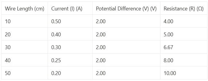
Analysis:
Plotting a graph of wire length (x-axis) against resistance (y-axis) will show a clear trend of increasing resistance with increasing wire length, confirming Ohm's Law.
2. Investigating Combinations of Resistors in Series and Parallel:
Materials Used:
Power supply
Ammeter
Voltmeter
Resistor (R1) with a resistance of 10 Ω
Resistor (R2) with a resistance of 20 Ω
Crocodile clips
Connecting wires
Example Data Table:
Series Combination:

Parallel Combination:

Analysis:
In the series combination, the total resistance is constant at 30 Ω, as expected since the resistors are connected end-to-end.
In the parallel combination, the total resistance is approximately 10 Ω, which is less than the smallest individual resistance (10 Ω and 20 Ω). This is in accordance with the principle that the total resistance in parallel is less than the smallest resistance.
By conducting these experiments and analysing the data, you can gain a deeper understanding of the factors affecting the resistance of electrical circuits and how different components behave when combined in series and parallel configurations. This practical experience helps reinforce the concepts of Ohm's Law and circuit behaviour, which are essential in the study of electricity and electronics.
Looking for a more dynamic learning experience?
Explore our engaging video lessons and interactive animations that GoPhysics has to offer – your gateway to an immersive physics education!
GCSE Physics Tutorial: Ohm's Law Equation
Ohm's Law is a fundamental principle in electrical circuits that describes the relationship between voltage (potential difference), current, and resistance. It provides a simple and powerful equation to calculate one of these parameters when the other two are known. In this tutorial, we will explore Ohm's Law and its equation.
1. Ohm's Law: Ohm's Law states that the current flowing through a conductor is directly proportional to the voltage (potential difference) across the conductor and inversely proportional to the resistance of the conductor. Mathematically, Ohm's Law can be expressed as follows:
V = I × R
where:
V: Represents the potential difference (voltage) across the conductor, measured in volts (V).
I: Denotes the current flowing through the conductor, measured in amperes (A).
R: Signifies the resistance of the conductor, measured in ohms (Ω).
2. Understanding the Equation:
The equation V = I × R indicates that the voltage across a conductor is equal to the current flowing through the conductor multiplied by its resistance.
If the voltage (V) across the conductor increases while the resistance (R) remains constant, the current (I) flowing through the conductor will also increase.
Similarly, if the voltage (V) across the conductor remains constant and the resistance (R) increases, the current (I) flowing through the conductor will decrease.
3. Practical Applications: Ohm's Law is extensively used in electrical engineering and electronics for circuit analysis, design, and troubleshooting.
It allows engineers to calculate the voltage, current, or resistance in a circuit when the other two values are known.
Ohm's Law is particularly valuable when working with resistors, conductors, and semiconductor devices, enabling engineers to predict and control the behaviour of components.
4. Units:
Voltage is measured in volts (V).
Current is measured in amperes (A).
Resistance is measured in ohms (Ω).
5. Summary:
Ohm's Law states that voltage (V) is equal to the current (I) multiplied by the resistance (R) in an electrical circuit.
The equation V = I × R is a powerful tool for calculating and understanding the behaviour of electrical components and circuits.
Ohm's Law is widely used in electrical engineering to analyse and design circuits, making it a fundamental principle in the study of electricity.
By understanding Ohm's Law and its equation, you can make informed decisions when working with electrical circuits and components. It provides a valuable tool for predicting and controlling current, voltage, and resistance in various electrical systems, allowing for efficient and safe design and operation of electronic devices and systems.
Looking for a more dynamic learning experience?
Explore our engaging video lessons and interactive animations that GoPhysics has to offer – your gateway to an immersive physics education!
GCSE Physics Tutorial: Understanding the Difference between Voltage and Potential Difference
In physics and electrical circuits, voltage and potential difference are related concepts, but they have distinct meanings and contexts. Understanding the difference between these terms is essential for accurately describing electrical phenomena and analysing circuits. In this tutorial, we will explore the key differences between voltage and potential difference.
1. Voltage:
Definition: Voltage is a measure of the electrical potential energy difference between two points in an electrical circuit. It represents the energy supplied or required to move a unit of electric charge from one point to another.
Symbol: The symbol for voltage is "V."
Units: Voltage is measured in volts (V) in the International System of Units (SI).
2. Potential Difference:
Definition: Potential difference is synonymous with voltage and represents the difference in electrical potential energy between two points in an electrical circuit. It signifies the change in electrical potential energy per unit of electric charge as it moves from one point to another.
Symbol: The symbol for potential difference is also "V."
Units: Like voltage, potential difference is measured in volts (V).
3. Key Difference: The main difference between voltage and potential difference is in the way the terms are used and interpreted in different contexts.
Voltage: Voltage is often used in a general sense when discussing electricity and electrical circuits. It describes the potential energy difference between two points, which can be across a component, a circuit, or a power source. For example, when we talk about the voltage of a battery, we refer to the potential energy difference between its positive and negative terminals.
Potential Difference: Potential difference is a more specific term used to describe the voltage between two points within a circuit or a component. It focuses on the energy difference experienced by electric charges as they move from one point to another. When we mention potential difference across a resistor or a capacitor, we refer to the specific energy difference experienced by the charges passing through that component.
4. Practical Application: Understanding the difference between voltage and potential difference is essential for analysing electrical circuits and calculating circuit parameters. By using the concept of potential difference, engineers and scientists can determine the energy changes experienced by electric charges as they move through various components in a circuit.
5. Summary:
Voltage and potential difference are related concepts, both representing the electrical potential energy difference between two points.
Voltage is a general term used to describe potential energy differences in electrical systems, while potential difference is more specific, focusing on energy changes between two points within a circuit or component.
By having a clear idea of the distinction between voltage and potential difference, you can communicate effectively when describing electrical phenomena and analysing electrical circuits. Both terms play significant roles in electrical engineering and are vital for understanding how electricity behaves in various applications.
Looking for a more dynamic learning experience?
Explore our engaging video lessons and interactive animations that GoPhysics has to offer – your gateway to an immersive physics education!
GCSE Physics Tutorial: Relation between Current, Resistance, and Potential Difference
In electrical circuits, the relationship between current, resistance, and potential difference (voltage) is governed by Ohm's Law. Understanding this relationship is fundamental for analysing and predicting the behaviour of electrical components in various circuits. In this tutorial, we will recall Ohm's Law and explore how current is dependent on both the resistance of a component and the potential difference across it.
1. Ohm's Law:
Ohm's Law is a fundamental principle in electricity that describes the relationship between current, resistance, and potential difference. It is expressed mathematically as:
V = I × R
where: V = Potential Difference (Voltage) across the component (in volts, V) I = Current flowing through the component (in amperes, A) R = Resistance of the component (in ohms, Ω)
2. Understanding Ohm's Law:
Ohm's Law states that the potential difference (voltage) across a component is directly proportional to the current flowing through it and the resistance of the component.
The potential difference (V) is the driving force that causes electric charges to move through a circuit. It represents the electrical energy provided to each coulomb of charge flowing through the component.
The current (I) is the rate at which electric charge flows through the component. It is a measure of the amount of charge passing a point in the circuit per second.
The resistance (R) represents the opposition encountered by the current as it flows through the component. It quantifies how much the component resists the flow of charge.
3. Dependency of Current on Resistance and Potential Difference:
Current is dependent on both the resistance of a component and the potential difference across it. According to Ohm's Law, the current flowing through a component is directly proportional to the potential difference and inversely proportional to the resistance. This can be expressed as:
I ∝ V / R
If the potential difference (V) across a component increases while the resistance (R) remains constant, the current (I) through the component will also increase.
Similarly, if the potential difference (V) remains constant and the resistance (R) increases, the current (I) through the component will decrease.
4. Practical Applications:
Ohm's Law is widely used in electrical engineering and electronics for circuit analysis and design. It enables engineers to calculate and predict current, voltage, and resistance in various circuits.
Ohm's Law is crucial for understanding how different components, such as resistors, conductors, and semiconductor devices, behave in electrical circuits.
Summary:
Ohm's Law (V = I × R) describes the relationship between current (I), resistance (R), and potential difference (V) in an electrical circuit.
Current is directly proportional to the potential difference and inversely proportional to the resistance according to Ohm's Law.
Understanding Ohm's Law is essential for predicting the behaviour of electrical components and analysing various electrical circuits.
By recalling Ohm's Law and understanding the relationship between current, resistance, and potential difference, you can gain valuable insights into the behaviour of electrical circuits and make informed decisions when designing, analysing, and troubleshooting various electrical systems. Ohm's Law is a foundational concept in the study of electricity and plays a key role in modern technology and engineering.
Looking for a more dynamic learning experience?
Explore our engaging video lessons and interactive animations that GoPhysics has to offer – your gateway to an immersive physics education!
GCSE Physics Tutorial: Current is the Same at Any Point in a Single Closed Loop
In electrical circuits, the flow of electric charge, known as current, follows specific rules and principles. One fundamental principle is that the current is the same at any point in a single closed loop. Understanding this concept is crucial for analyzing and troubleshooting electrical circuits. In this tutorial, we will explore the significance of current being constant within a single closed loop.
1. Closed Loop:
A closed loop is a continuous pathway through which electric charges can flow. It forms a complete circuit, allowing the current to circulate from the power source through various components and back to the power source. A closed loop ensures the continuity of the electric circuit, enabling the flow of charges.
2. Conservation of Charge:
The principle of conservation of charge states that electric charge cannot be created or destroyed. In an electric circuit, the total amount of charge entering a closed loop must be equal to the total amount of charge leaving the loop. This principle ensures that the flow of electric charge remains constant within a single closed loop.
3. Kirchhoff's Current Law (KCL):
Kirchhoff's Current Law, also known as the junction rule, is a fundamental law in electrical circuit analysis. It states that the total current entering a junction (or node) in an electrical circuit is equal to the total current leaving the junction. Mathematically, this can be represented as:
$$Σ I_{in} = Σ I_{out}$$
where: $Σ I_{in}$ = Sum of currents entering the junction $Σ I_{out}$ = Sum of currents leaving the junction
4. Current in Series and Parallel Circuits:
In a series circuit, where components are connected in a single closed loop, the current is the same at any point in the circuit. This is because there is only one path for the current to flow.
In a parallel circuit, where components are connected in multiple closed loops, the current may vary at different points in the circuit. However, the total current entering a junction must be equal to the total current leaving the junction, as stated by Kirchhoff's Current Law.
5. Application in Circuit Analysis:
The principle that current is the same at any point in a single closed loop is valuable in analyzing and solving electrical circuits. By knowing the current at one point in the loop, you can determine the current at any other point within the same loop.
This principle also aids in identifying the relationship between currents and resistances in series and parallel circuits, making it essential for designing and understanding complex electrical systems.
Summary:
Current is constant at any point within a single closed loop in an electrical circuit.
Kirchhoff's Current Law states that the total current entering a junction must be equal to the total current leaving the junction.
Understanding this principle is essential for circuit analysis, troubleshooting, and designing electrical circuits.
By grasping the concept that current is the same at any point in a single closed loop, you can gain insights into the behavior of electrical circuits and confidently apply Kirchhoff's laws to analyze and solve complex circuit problems.
Looking for a more dynamic learning experience?
Explore our engaging video lessons and interactive animations that GoPhysics has to offer – your gateway to an immersive physics education!
GCSE Physics Tutorial: Units for Current, Charge, and Time
In physics, understanding and using the correct units for various quantities are crucial for accurate measurements and calculations. In this tutorial, we will recall the units for current, electric charge, and time, which are essential concepts when working with electricity.
1. Current (I):
Unit: The unit for electric current is the ampere (A).
Symbol: The symbol for ampere is "A".
Definition: One ampere (1 A) of current represents the flow of one coulomb of electric charge per second through a conductor.
2. Electric Charge (Q):
Unit: The unit for electric charge is the coulomb (C).
Symbol: The symbol for coulomb is "C".
Definition: One coulomb (1 C) of electric charge is equivalent to approximately 6.24 x 10^18 elementary charges (e) or the charge of one mole of electrons.
3. Time (t):
Unit: The unit for time is the second (s).
Symbol: The symbol for second is "s".
Definition: One second (1 s) is the base unit of time in the International System of Units (SI). It is defined as the duration of 9,192,631,770 periods of the radiation corresponding to the transition between two hyperfine levels of the ground state of the cesium-133 atom.
Summary:
Current is measured in amperes (A).
Electric charge is measured in coulombs (C).
Time is measured in seconds (s).
Practical Applications:
When working with electrical circuits, you use amperes to measure the current flowing through the circuit using an ammeter.
Coulombs are used to quantify the amount of electric charge that has passed through a component or a circuit during a specific time period.
Seconds are commonly used to measure the time taken for various electrical processes, such as the charging or discharging of a capacitor or the duration of an electrical event.
Important Note:
When performing calculations, ensure that the units for current, electric charge, and time are consistent. Always pay attention to the units and conversions to obtain accurate results.
In some situations, milliamperes (mA) and microamperes (μA) may also be used to measure small currents, where 1 mA is equal to 0.001 A, and 1 μA is equal to 0.000001 A.
Understanding and using the correct units is fundamental in physics, and it allows scientists and engineers to communicate effectively, conduct experiments, and make accurate measurements in various scientific and engineering fields, including electricity and electronics.
Looking for a more dynamic learning experience?
Explore our engaging video lessons and interactive animations that GoPhysics has to offer – your gateway to an immersive physics education!
GCSE Physics Tutorial: Applying the Equation for Current Flow
In the previous tutorial, we learned about the definition of current and the mathematical relationship between current (I), electric charge (Q), and time (t). In this tutorial, we will explore how to apply the equation for current flow in practical scenarios involving electrical circuits.
1. Equation for Current Flow: The equation for current flow is given by:
I = Q / twhere: I = Current (in amperes, A) Q = Electric charge (in coulombs, C) t = Time (in seconds, s)
2. Example 1: Calculating Current: Let's apply the equation to a simple scenario. Suppose a circuit carries an electric charge of 200 coulombs in 10 seconds. To find the current flowing in the circuit, we can use the equation:
I = Q / t
I = 200 C / 10 s
I = 20 A
The current flowing in the circuit is 20 amperes.
3. Example 2: Calculating Charge: Conversely, if we know the current and the time, we can calculate the electric charge. For instance, if a circuit has a current of 5 amperes flowing through it for 15 seconds, we can determine the charge using the same equation:
I = Q / t
5 A = Q / 15 s
Q = 5 A x 15 s
Q = 75 C
The electric charge in the circuit is 75 coulombs.
4. Real-World Application: Battery Charging The equation for current flow is commonly used in scenarios involving battery charging. When charging a battery, the charging current (I) and the time (t) are essential parameters. By measuring the current and knowing the charging time, one can calculate the amount of charge supplied to the battery during the charging process.
5. Using an Ammeter: To apply the current equation practically, you need to measure the current in a circuit. This is done using an ammeter, a device specifically designed to measure electric current. An ammeter should be connected in series with the component or the circuit you want to measure the current flowing through.
6. Units: Ensure that the units for current (I), electric charge (Q), and time (t) are consistent. For example, use amperes (A) for current, coulombs (C) for charge, and seconds (s) for time.
7. Summary: The equation for current flow (I = Q / t) is a fundamental tool in understanding and analysing electrical circuits. It allows us to calculate the current flowing in a circuit or the electric charge carried by the current over a given time. Applying this equation enables us to make informed decisions in designing and troubleshooting electrical systems, making it a crucial aspect of working with electricity.
Note: Be cautious and ensure safety while working with electricity. Always disconnect the circuit before measuring or making changes to avoid electric shock or damage to equipment.
Looking for a more dynamic learning experience?
Explore our engaging video lessons and interactive animations that GoPhysics has to offer – your gateway to an immersive physics education!
GCSE Physics Tutorial: Definition of Current
Current is a fundamental concept in electricity and is a measure of the flow of electric charge through a conducting medium. Understanding current is essential for comprehending the behaviour of electrical circuits and how electricity is utilised in various applications. In this tutorial, we will define current and explore its key aspects.
1. Definition of Current:
Current (I): Current is the rate of flow of electric charge through a conductor. It is measured in amperes (A), where 1 ampere is defined as the flow of 1 coulomb of charge per second.
2. Electric Charge (Q):
Electric Charge: Electric charge is a fundamental property of matter that can be positive or negative. The elementary unit of electric charge is the charge of an electron, which is approximately -1.6 x 10^-19 coulombs (C).
Coulomb (C): The coulomb is the SI unit of electric charge. It represents the quantity of charge when 1 ampere of current flows for 1 second. One coulomb is equal to the charge of approximately 6.24 x 10^18 electrons.
3. Mathematical Relationship: The relationship between current (I), electric charge (Q), and time (t) can be expressed using the following formula:
I=Qt
where: I = Current (in amperes, A) Q = Electric charge (in coulombs, C) t = Time (in seconds, s)
4. Direction of Current:
Current is defined as the flow of positive charge carriers. In most conductors, such as metals, the charge carriers are electrons, which have a negative charge. Therefore, the direction of current flow is opposite to the movement of electrons. This convention, known as conventional current flow, assumes that current moves from the positive to the negative terminal of a circuit.
5. Measuring Current:
Current is measured using a device called an ammeter. An ammeter is connected in series with the circuit, allowing it to measure the current flowing through a specific component or the entire circuit.
6. Units of Current:
The SI unit of current is the ampere (A). Smaller currents are often measured in milliamperes (mA), where 1 mA is equal to 0.001 amperes. Larger currents may be expressed in kiloamperes (kA), where 1 kA is equal to 1000 amperes.
Conclusion: Current is the flow of electric charge through a conductor and is measured in amperes. It represents the rate at which electric charge moves, and it plays a central role in understanding electrical circuits and the behaviour of electrical systems. By grasping the concept of current, you can gain insight into how electricity is used, transmitted, and controlled in various applications, making it a fundamental aspect of studying physics and electrical engineering.
Looking for a more dynamic learning experience?
Explore our engaging video lessons and interactive animations that GoPhysics has to offer – your gateway to an immersive physics education!
GCSE Physics Tutorial: Requirements for Electrical Charge Flow
Electric charge flow is the movement of electric charges through a conducting material in response to an electric potential difference (voltage). Understanding the requirements for electrical charge flow is essential for comprehending how electricity works and how current is established in a circuit. In this tutorial, we will define the requirements for electrical charge flow.
1. Electric Potential Difference (Voltage):
Definition: Electric potential difference, commonly known as voltage, is the driving force that pushes electric charges to move in a circuit. It is measured in volts (V).
Requirement: To establish charge flow, there must be a difference in electric potential between two points in a circuit. The potential difference creates an electric field that exerts a force on the electric charges, causing them to move from areas of higher potential to areas of lower potential.
2. Conducting Medium:
Definition: A conducting medium is a material that allows the free movement of electric charges, also known as charge carriers. Metals, such as copper and aluminum, are excellent conductors of electricity due to their abundance of free electrons that can move easily within the material.
Requirement: For charge flow to occur, there must be a conducting medium that enables the movement of electric charges through it. Insulators, on the other hand, do not allow charge flow as their electrons are tightly bound and cannot move freely.
3. Closed Circuit:
Definition: A closed circuit is a complete pathway for electric charges to flow from a power source through various components and back to the power source.
Requirement: To sustain charge flow, the circuit must be closed and continuous, allowing a loop for the charges to follow. If there is an interruption or an open circuit, charge flow will cease, and no current will be established.
4. Electric Field:
Definition: An electric field is a region around a charged object or between charged objects where electric forces are exerted on other charged particles.
Requirement: An electric field is necessary to establish charge flow. When a potential difference exists between two points in a circuit, it creates an electric field that exerts a force on the electric charges, propelling them through the conducting medium.
5. Driving Force (EMF - Electromotive Force):
Definition: Electromotive force (EMF) is a term often used to describe the energy supplied by a power source, such as a battery or generator, to drive electric charges in a circuit.
Requirement: The presence of an EMF is necessary to maintain a continuous flow of electric charges in the circuit. It provides the energy needed to push the charges against resistance and maintain a steady current.
6. Charge Carriers:
Definition: Charge carriers are mobile electric charges within a conducting medium. In most conductors, electrons act as charge carriers, while in some cases, positively charged ions may also act as charge carriers.
Requirement: For charge flow to occur, there must be charge carriers present in the conducting medium. The electric field causes these charge carriers to move and create an electric current.
Conclusion: Electrical charge flow requires several key elements to be present and interact within a circuit. These include a potential difference (voltage), a conducting medium, a closed circuit pathway, an electric field, a driving force (EMF), and charge carriers. Understanding these requirements is fundamental to grasping the principles of electricity and how electric current is established and flows in electrical circuits.
Looking for a more dynamic learning experience?
Explore our engaging video lessons and interactive animations that GoPhysics has to offer – your gateway to an immersive physics education!
GCSE Physics Tutorial: Explaining Additional Components in Electrical Circuits
In this tutorial, we will explore additional components that you may encounter in electrical circuits, such as motors, buzzers, heaters, and more. While these components may not have been covered in previous examples, we will explain their purpose in the context of the question.
1. Motor:
Purpose: A motor is an electromechanical device that converts electrical energy into mechanical energy. When current flows through the motor, it generates a magnetic field that interacts with the magnetic field of the motor's coils, causing the motor shaft to rotate. This rotational motion can be used to drive various mechanical systems, such as fans, wheels, or conveyor belts.
2. Buzzer:
Purpose: A buzzer is an audio signaling device that produces a continuous or intermittent sound when an electrical current passes through it. The buzzer typically consists of an electromagnetic coil and a diaphragm. The alternating magnetic field created by the current causes the diaphragm to vibrate rapidly, producing sound waves that we perceive as a buzzing sound.
3. Heater:
Purpose: A heater is a device designed to convert electrical energy into heat. It consists of a resistive element through which the current passes. As the current flows through the resistor, it encounters resistance, leading to the production of heat. Heaters are commonly used in applications such as electric stoves, water heaters, and room heaters.
4. Relay:
Purpose: A relay is an electrically operated switch used to control a high-power circuit using a low-power signal. It consists of an electromagnet and a set of contacts. When current flows through the coil, the electromagnet becomes magnetised, causing the contacts to close or open, depending on the relay type. Relays are commonly used in control circuits for various applications, such as automotive systems, home automation, and industrial machinery.
5. Capacitor:
Purpose: A capacitor is an electronic component that stores electrical energy in an electric field. It consists of two conductive plates separated by an insulating material (dielectric). When a voltage is applied across the plates, the capacitor charges and stores energy. Capacitors are used in various applications, such as filtering electrical noise, smoothing voltage fluctuations, and timing circuits.
6. Diode:
Purpose: A diode is a semiconductor device that allows current to flow in one direction only. It acts as a one-way valve for electrical current. When the voltage across the diode is in the forward direction, the diode conducts current; otherwise, it blocks the current flow. Diodes are commonly used for rectification in power supplies, voltage regulation, and protection circuits.
7. Transistor:
Purpose: A transistor is a semiconductor device used as an amplifier or switch in electronic circuits. It can control the flow of current between two terminals (collector and emitter) based on the voltage applied to the third terminal (base). Transistors play a crucial role in amplifying weak signals in audio and radio-frequency applications, as well as in digital logic circuits.
Conclusion: While studying electrical circuits, you may encounter various components not covered in basic examples. Understanding the purpose and function of these components is essential for comprehending their role in different applications. Components like motors, buzzers, heaters, relays, capacitors, diodes, and transistors have specific functions that contribute to the functionality and operation of electrical and electronic systems. Keep exploring and practicing with various components to expand your knowledge and skills in circuit analysis and design.
Looking for a more dynamic learning experience?
Explore our engaging video lessons and interactive animations that GoPhysics has to offer – your gateway to an immersive physics education!
GCSE Physics Tutorial: Components in Circuits
In this tutorial, we will learn how to draw and identify various components commonly used in electrical circuits, including variable resistors, LEDs, lamps, fuses, voltmeters, ammeters, thermistors, and LDRs.
1. Variable Resistor:
Symbol: The variable resistor is represented by a rectangular shape with an arrow pointing towards the middle. The arrow indicates the adjustable or variable nature of the resistor.
2. LED (Light Emitting Diode):
Symbol: The LED is depicted as a diode with two arrows pointing away from it. The arrows represent the light emitted by the LED when a current passes through it.
3. Lamp:
Symbol: The lamp is represented by a circle with a cross inside. The cross indicates the filament inside the lamp, which emits light when current passes through it.
4. Fuse:
Symbol: The fuse is depicted as a squiggly line inside a rectangle. The squiggly line represents the fuse wire that melts when the current exceeds a safe value, breaking the circuit to protect it from excessive current flow.
5. Voltmeter:
Symbol: The voltmeter is represented by a circle with a V inside. The circle indicates that the voltmeter measures voltage across a component in a circuit.
6. Ammeter:
Symbol: The ammeter is depicted by a circle with an A inside. The circle indicates that the ammeter measures the current flowing through a component in a circuit.
7. Thermistor:
Symbol: The thermistor is represented by a resistor symbol with a line passing through it. The line represents the temperature-sensitive material inside the thermistor, which changes resistance with temperature.
8. LDR (Light Dependent Resistor):
Symbol: The LDR is depicted as a resistor symbol with an arrow and a circle on one side. The arrow indicates that the resistance of the LDR changes with light intensity.
Remember to properly label the components in your circuit diagrams to indicate their purpose and function.
Keep in mind that drawing accurate circuit diagrams is an essential skill in understanding electrical circuits and their components. Practice drawing various circuit configurations to reinforce your knowledge and improve your skills in circuit analysis.
Looking for a more dynamic learning experience?
Explore our engaging video lessons and interactive animations that GoPhysics has to offer – your gateway to an immersive physics education!
GCSE Physics Tutorial: Identifying and Addressing Environmental Issues from Energy Resources
Science plays a vital role in identifying environmental issues arising from energy resources by providing objective data, conducting research, and analysing the impacts. However, science alone does not always have the power to deal with these issues due to various external factors, such as political, social, ethical, and economic considerations. In this tutorial, we will explore why science can identify environmental issues but faces limitations in addressing them fully.
1. Identifying Environmental Issues: Science, through rigorous research and data analysis, can identify environmental issues associated with different energy resources:
Data Collection: Scientists gather data on greenhouse gas emissions, air and water pollution, habitat destruction, and other environmental impacts from energy production and consumption.
Research Studies: Studies examine the effects of various energy resources on ecosystems, climate, and human health, providing valuable insights into potential risks.
Environmental Impact Assessments: Scientists conduct environmental impact assessments to evaluate the consequences of energy projects and inform decision-making.
2. Limitations in Addressing Environmental Issues: While science identifies environmental issues, addressing them fully can be hindered by several factors:
a) Political Considerations:
Policy Formulation: Policy decisions related to energy resources are often influenced by political considerations and agendas, which may not prioritise environmental concerns.
Regulatory Enforcement: The implementation and enforcement of environmental regulations can be influenced by political will and lobbying efforts, affecting their effectiveness.
b) Social Considerations:
Public Perception: Public attitudes towards certain energy resources, such as nuclear energy or wind farms, can influence the acceptance and implementation of environmentally friendly alternatives.
Social Impact: Energy projects may face opposition from local communities concerned about issues like displacement, visual impacts, or cultural heritage.
c) Ethical Considerations:
Environmental Justice: Environmental decisions may raise ethical questions about the distribution of environmental benefits and burdens across different communities.
Interests of Stakeholders: Ethical considerations may arise when balancing the interests of various stakeholders, including industry, environmental groups, and affected communities.
d) Economic Considerations:
Cost-Benefit Analysis: Economic considerations often involve cost-benefit analyses, where the economic benefits of certain energy resources may be prioritised over environmental concerns.
Investment in Transition: Transitioning to cleaner energy sources may require significant financial investments and may face resistance due to economic considerations.
3. Interplay of Factors: The ability to address environmental issues involves a complex interplay of political, social, ethical, and economic factors, which can influence policy decisions and the allocation of resources.
Conclusion: Science, with its objective analysis and research, can identify environmental issues arising from energy resources. However, addressing these issues requires navigating a complex landscape of political, social, ethical, and economic considerations. Achieving a sustainable and environmentally responsible energy future necessitates collaboration between scientific experts, policymakers, stakeholders, and the public. By striking a balance between environmental concerns and societal needs, we can work towards effective and practical solutions that minimise the environmental impacts of energy resources while ensuring the stability and growth of our societies.
Looking for a more dynamic learning experience?
Explore our engaging video lessons and interactive animations that GoPhysics has to offer – your gateway to an immersive physics education!
GCSE Physics Tutorial: Environmental Issues from the Use of Different Energy Resources
Energy resources play a critical role in powering our modern society, but their utilisation can have various environmental impacts. Different energy resources have distinct environmental issues associated with their extraction, production, consumption, and waste management. In this tutorial, we will describe possible environmental issues that may arise from the use of different energy resources.
1. Fossil Fuels:
Air Pollution: Combustion of fossil fuels releases carbon dioxide (CO2), sulfur dioxide (SO2), nitrogen oxides (NOx), particulate matter, and volatile organic compounds (VOCs), leading to air pollution and smog formation.
Climate Change: The release of CO2 and other greenhouse gases from burning fossil fuels contributes to global warming and climate change, leading to rising temperatures, melting ice caps, and more frequent extreme weather events.
Water Pollution: Oil spills from offshore drilling and accidents can result in water pollution, damaging marine ecosystems and coastal habitats.
Land Degradation: Mining activities for coal and other fossil fuels can cause habitat destruction and soil contamination, disrupting local ecosystems.
2. Nuclear Energy:
Radioactive Waste: Nuclear power generation produces radioactive waste that requires secure long-term storage and disposal, posing challenges for managing nuclear waste.
Accidents and Disasters: The possibility of nuclear accidents, such as Chernobyl and Fukushima, raises concerns about radiation release and potential long-term environmental consequences.
3. Renewable Energy Resources:
Solar Energy: The production of solar panels involves energy-intensive processes and the use of hazardous materials, requiring proper recycling and disposal practices.
Wind Energy: Wind farms may affect local wildlife and bird populations, and their installation can require habitat disruption.
Hydropower: Large-scale hydropower projects can lead to habitat destruction, impact fish migration, and displace communities living near the dam sites.
Geothermal Energy: Drilling for geothermal energy may disrupt subsurface ecosystems and release geothermal fluids that require proper disposal.
Biomass Energy: Unsustainable biomass practices, such as deforestation for energy crop production, can lead to habitat loss and carbon emissions.
Tidal Energy: Tidal energy projects may affect marine ecosystems and navigation, requiring careful site selection and impact assessment.
4. Overall Environmental Considerations:
Biodiversity Loss: Habitat destruction and pollution from various energy resources can lead to the loss of plant and animal species, reducing biodiversity.
Ocean Acidification: CO2 absorption by the oceans leads to acidification, affecting marine life and ecosystems.
Resource Depletion: Non-renewable energy resources, like coal, oil, and natural gas, are finite and will eventually deplete, necessitating a transition to sustainable alternatives.
Climate Change: The cumulative impact of greenhouse gas emissions from all energy resources contributes to global climate change and its associated effects on the environment.
Conclusion: Different energy resources have diverse environmental impacts, ranging from air and water pollution to habitat destruction and climate change. Fossil fuels contribute significantly to greenhouse gas emissions and air pollution, while nuclear energy raises concerns about radioactive waste management and safety. Renewable energy resources offer cleaner alternatives, but their use also comes with specific environmental considerations, such as habitat disruption and waste management. As we seek to address these environmental issues, transitioning to sustainable and renewable energy sources becomes crucial for mitigating the impacts of energy production on the environment and creating a more sustainable and environmentally responsible energy future.
Looking for a more dynamic learning experience?
Explore our engaging video lessons and interactive animations that GoPhysics has to offer – your gateway to an immersive physics education!
GCSE Physics Tutorial: Patterns of Energy Resources and Their Consequences
Patterns of energy resource use and environmental changes are shaped by various factors, including human behaviour, technological advancements, economic activities, and geographic considerations. Understanding these patterns can provide insights into our energy consumption and its impact on the environment. In this tutorial, we will explore some reasons behind certain energy resource patterns and their consequences.
1. High Use of Energy at 5 pm in the UK: The high use of energy at 5 pm in the UK can be attributed to several factors:
a) Evening Peak Demand: 5 pm marks the evening peak demand for energy in residential and commercial areas. During this time, people return home from work, leading to increased electricity usage for lighting, cooking, heating, and entertainment.
b) Time of Day Tariffs: Some energy providers offer time-of-day tariffs, where electricity prices are higher during peak hours (e.g., 4 pm to 7 pm). This encourages consumers to shift their energy-intensive activities to off-peak hours, helping to balance energy demand throughout the day.
c) Industrial Activities: Energy-intensive industries and manufacturing plants may be operating at full capacity during daytime hours, contributing to increased energy demand.
d) Seasonal Variation: The time of sunset varies throughout the year. During the winter months, darkness falls earlier, resulting in higher energy use for lighting and heating.
2. Increase in Carbon Dioxide Levels with Fossil Fuel Use: The increase in carbon dioxide (CO2) levels is linked to the burning of fossil fuels:
a) Greenhouse Gas Emissions: Fossil fuels (coal, oil, natural gas) are carbon-rich substances. When burned for electricity generation, transportation, and heating, they release CO2 and other greenhouse gases into the atmosphere.
b) Enhanced Greenhouse Effect: The accumulation of greenhouse gases, including CO2, traps heat in the Earth's atmosphere, leading to the enhanced greenhouse effect. This causes global warming and climate change, as more heat is retained, resulting in rising temperatures and shifts in weather patterns.
c) Historical Energy Choices: The industrial revolution and subsequent economic growth were heavily reliant on fossil fuels, contributing to the significant increase in their consumption and CO2 emissions.
d) Economic Development and Population Growth: As countries develop and populations grow, energy demands increase, often leading to greater fossil fuel use and subsequent CO2 emissions.
e) Limited Alternatives: Until recently, renewable energy technologies were less developed and more expensive, leading to continued reliance on fossil fuels. However, as renewable energy becomes more cost-effective and accessible, the transition to cleaner alternatives is gaining momentum.
Consequences of High Carbon Dioxide Levels: The consequences of increasing CO2 levels are significant and include:
Climate Change: Rising temperatures, melting glaciers, and more frequent extreme weather events are consequences of global climate change driven by increased CO2 levels.
Ocean Acidification: CO2 absorption by the oceans leads to ocean acidification, affecting marine life and ecosystems.
Biodiversity Loss: Climate change and habitat disruption caused by increasing CO2 levels threaten biodiversity, leading to species extinction and ecosystem imbalances.
Health Impacts: Poor air quality resulting from CO2 emissions and other pollutants contributes to respiratory and cardiovascular health issues in humans.
Conclusion: The patterns of energy resource use, such as high energy demand at 5 pm, and the increase in carbon dioxide levels due to fossil fuel use are influenced by a combination of human behaviour, economic activities, technological choices, and geographic factors. As we understand these patterns and their consequences, it becomes crucial to prioritise sustainable energy practices, transition to cleaner alternatives, and adopt energy-efficient technologies. By doing so, we can mitigate the environmental impacts of our energy consumption and pave the way towards a more sustainable and environmentally responsible future.
Looking for a more dynamic learning experience?
Explore our engaging video lessons and interactive animations that GoPhysics has to offer – your gateway to an immersive physics education!
GCSE Physics Tutorial: Environmental Impact of Different Energy Resources
Energy resources have varying environmental impacts depending on their extraction, production, and consumption processes. Understanding the environmental impact of different energy resources is crucial for making informed decisions about sustainable energy solutions. In this tutorial, we will describe the environmental impact arising from various energy resources.
1. Fossil Fuels:
Coal: Burning coal for electricity and heat generation releases large amounts of carbon dioxide (CO2), sulfur dioxide (SO2), nitrogen oxides (NOx), and particulate matter. These emissions contribute to air pollution, acid rain, and climate change.
Oil: The extraction, refining, and combustion of oil-based products (e.g., gasoline, diesel) emit CO2, SO2, NOx, volatile organic compounds (VOCs), and other pollutants. Oil spills can have catastrophic effects on marine ecosystems.
Natural Gas: While natural gas produces fewer CO2 emissions than coal and oil, it still releases greenhouse gases. Methane leaks during extraction and distribution also contribute to climate change.
2. Nuclear Energy:
Nuclear Waste: Nuclear power plants generate radioactive waste that requires careful management and long-term storage. Safe disposal of nuclear waste is a significant environmental concern.
3. Renewable Energy Resources:
Solar Energy: Solar panels have a minimal impact during operation, but their production involves energy-intensive processes and the use of hazardous materials. Proper recycling and disposal of end-of-life solar panels are essential.
Wind Energy: Wind turbines have a relatively low environmental impact during operation, but their manufacturing and installation may have some effects on local ecosystems and landscapes.
Hydropower: Large-scale hydropower projects can alter river ecosystems and impact fish migration. The construction of dams may also displace communities and result in habitat destruction.
Geothermal Energy: Geothermal power plants have low greenhouse gas emissions during operation. However, some projects require drilling and can cause subsurface ecosystem disturbances.
Biomass Energy: The environmental impact of biomass depends on the source. Sustainable biomass from waste materials or dedicated energy crops is more favorable than using valuable food crops or promoting deforestation.
Tidal Energy: Tidal energy has minimal greenhouse gas emissions and a low environmental impact during operation. It can, however, affect marine ecosystems and navigation.
4. Overall Environmental Considerations:
Climate Change: The release of greenhouse gases, primarily CO2 and methane, from fossil fuel combustion contributes to global warming and climate change.
Air Pollution: Emissions of SO2, NOx, VOCs, and particulate matter from fossil fuels lead to air pollution, smog, and respiratory issues.
Water Pollution: Some energy resources, like coal mining and oil extraction, can result in water pollution due to runoff and spills.
Habitat Destruction: The construction of large-scale energy projects, such as dams and wind farms, can lead to habitat destruction and ecosystem alterations.
Biodiversity Loss: Habitat destruction and pollution can result in the loss of plant and animal species, affecting biodiversity.
Conclusion: Different energy resources have varied environmental impacts, with fossil fuels being major contributors to air pollution, climate change, and habitat destruction. Nuclear energy has concerns related to radioactive waste management. Renewable energy resources offer cleaner alternatives, but they are not entirely without environmental impacts, such as materials extraction and land use. Striking a balance between meeting our energy needs and minimising environmental impacts requires transitioning towards a more sustainable energy mix, emphasising energy efficiency, and adopting technologies that reduce greenhouse gas emissions and preserve natural ecosystems.
Looking for a more dynamic learning experience?
Explore our engaging video lessons and interactive animations that GoPhysics has to offer – your gateway to an immersive physics education!
GCSE Physics Tutorial: Reliability of Energy Resources
The reliability of energy resources refers to their ability to consistently and predictably provide the necessary energy output when required. Some energy resources are more reliable than others, and this reliability is crucial for meeting our energy demands effectively. In this tutorial, we will explore the factors that influence the reliability of energy resources and compare different sources based on their dependability.
1. Factors Affecting Reliability: Several factors influence the reliability of energy resources:
a) Availability: Reliable energy resources should be readily available to meet our energy needs consistently. This availability can be affected by factors such as location, seasonal variations, and geological conditions.
b) Intermittency: Some renewable energy resources, like solar and wind, are intermittent and depend on weather conditions. Their reliability may vary based on the time of day, weather patterns, and geographic location.
c) Storage Capacity: The ability to store excess energy for use during periods of low production or high demand enhances the reliability of certain energy resources, especially renewables.
d) Redundancy and Grid Stability: A reliable energy system should have redundancies and a stable grid infrastructure to ensure continuous supply, even in the event of disruptions or failures.
2. Reliability of Different Energy Resources: Let's compare the reliability of various energy resources:
a) Fossil Fuels:
Reliability: Fossil fuels, such as coal, oil, and natural gas, are traditionally considered reliable energy sources. They provide a stable and continuous energy supply due to their high energy density and consistent availability.
Concerns: However, their reliance on finite resources and environmental impact, including greenhouse gas emissions and pollution, raise concerns about long-term reliability and sustainability.
b) Nuclear Energy:
Reliability: Nuclear power is generally considered reliable, as nuclear plants can operate continuously for extended periods, providing a stable energy supply.
Concerns: The potential for nuclear accidents and the management of radioactive waste pose significant challenges to the long-term reliability and safety of nuclear energy.
c) Renewable Energy Resources:
Solar Energy: Solar energy's reliability depends on the availability of sunlight. It is highly reliable in regions with consistent sunshine but may be less reliable in areas with frequent cloud cover.
Wind Energy: Wind energy's reliability depends on wind patterns. Wind power can be highly reliable in suitable locations with consistent wind speeds.
Hydropower: Hydropower is considered one of the most reliable renewable energy sources due to its continuous supply of water, although droughts can affect its availability.
Geothermal Energy: Geothermal energy is reliable, providing continuous power, but its availability is limited to regions with accessible geothermal resources.
Biomass Energy: Biomass energy can be considered reliable when waste materials are used, but its availability may vary based on biomass production and sustainability practices.
Tidal Energy: Tidal energy is predictable and reliable, as tidal patterns follow astronomical cycles.
3. Enhancing Reliability:
Diversification: A mix of energy resources, including renewables and conventional sources, can enhance overall energy reliability by reducing dependence on a single resource.
Energy Storage: Developing efficient energy storage technologies allows excess energy to be stored and utilised during periods of high demand or low production, improving the reliability of intermittent resources.
Grid Infrastructure: Ensuring a robust and well-maintained grid infrastructure is crucial for stable and reliable energy transmission.
Conclusion: The reliability of energy resources depends on various factors, including their availability, intermittency, storage capacity, and grid stability. While fossil fuels and nuclear energy have historically been considered reliable, the growing focus on renewable energy aims to address concerns about environmental impact and resource depletion. Advances in energy storage and grid infrastructure further improve the reliability of renewables. A diversified and sustainable energy mix, combining both reliable and intermittent sources, is essential for meeting our energy needs efficiently and ensuring a stable and secure energy future.
Looking for a more dynamic learning experience?
Explore our engaging video lessons and interactive animations that GoPhysics has to offer – your gateway to an immersive physics education!
GCSE Physics Tutorial: Comparing Different Energy Resources and Their Uses
Energy resources vary in their availability, environmental impact, and efficiency in generating power. It is essential to compare different energy resources to understand their advantages and limitations. Some energy resources can be used in ways that are better than others based on specific criteria, such as sustainability, cost, and environmental impact. In this tutorial, we will compare various energy resources and explore their uses, as well as their potential strengths and weaknesses.
1. Fossil Fuels:
Uses: Fossil fuels (coal, oil, natural gas) are widely used for electricity generation, transportation, heating, and industrial processes.
Strengths: Fossil fuels have high energy density, making them a reliable and readily available energy source. They have been the backbone of energy supply for decades.
Weaknesses: Fossil fuels are non-renewable and contribute to environmental issues like air pollution and greenhouse gas emissions. Their extraction, transportation, and use pose environmental and safety challenges.
2. Renewable Energy Resources:
Solar Energy:
Uses: Solar energy is used for electricity generation through solar panels and solar thermal systems for water heating.
Strengths: Solar energy is abundant, clean, and sustainable. It is harnessed through photovoltaic cells, causing no greenhouse gas emissions during operation.
Weaknesses: Solar energy generation is intermittent and weather-dependent. The production of solar panels requires some energy-intensive processes.
Wind Energy:
Uses: Wind energy is utilised for electricity generation using wind turbines, especially in wind farms.
Strengths: Wind energy is a renewable and clean resource, emitting no greenhouse gases during operation. It is abundant in certain regions.
Weaknesses: Wind energy generation is location-dependent and can be affected by wind patterns. Visual and noise impacts are considered in some areas.
Hydropower:
Uses: Hydropower generates electricity using flowing water through hydroelectric power plants.
Strengths: Hydropower is a reliable and renewable energy source. It offers flexibility in power generation and can store energy for peak demand.
Weaknesses: The construction of large dams may have environmental and social impacts on aquatic ecosystems and communities.
Geothermal Energy:
Uses: Geothermal power plants generate electricity using heat from the Earth's interior.
Strengths: Geothermal energy is sustainable and emits very low greenhouse gas emissions during operation. It provides continuous power.
Weaknesses: Geothermal resources are location-specific and may require exploration to identify suitable sites.
Biomass Energy:
Uses: Biomass energy is used for heating, electricity generation, and biofuels.
Strengths: Biomass is renewable, and certain waste materials can be used as a fuel source, reducing waste disposal issues.
Weaknesses: Biomass energy may compete with food production and can lead to deforestation if not sustainably managed.
3. Tidal Energy:
Uses: Tidal energy is harnessed using tidal turbines to generate electricity in coastal areas.
Strengths: Tidal energy is predictable, reliable, and renewable, with minimal environmental impact during operation.
Weaknesses: Tidal energy generation is site-specific and limited to regions with significant tidal fluctuations.
Conclusion: Comparing different energy resources is essential to understand their unique attributes and potential uses. Fossil fuels have been reliable but come with environmental challenges. Renewable energy resources offer cleaner and more sustainable alternatives, each with its own advantages and limitations. Some energy resources, like solar and wind, can be harnessed in ways that are better than others, as they provide clean, sustainable, and abundant energy with reduced environmental impact. The transition towards greater use of renewable energy is crucial for addressing environmental concerns, ensuring energy security, and building a more sustainable future.
Looking for a more dynamic learning experience?
Explore our engaging video lessons and interactive animations that GoPhysics has to offer – your gateway to an immersive physics education!
GCSE Physics Tutorial: Examples of How Energy Resources Are Used in Everyday Life
Energy resources play a central role in our daily lives, powering various devices, systems, and appliances that we rely on for comfort, convenience, and productivity. From lighting our homes to powering transportation, energy resources are integral to modern living. In this tutorial, we will explore examples of how energy resources are used in everyday life.
1. Electricity: Electricity, a versatile form of energy, is used in numerous ways in our daily routines:
Lighting: Electric energy powers lighting fixtures, allowing us to illuminate our homes, offices, streets, and public spaces.
Home Appliances: We use electric energy to operate appliances like refrigerators, washing machines, microwaves, air conditioners, and televisions.
Computers and Devices: Laptops, smartphones, tablets, and other electronic devices run on electricity, enabling communication, work, and entertainment.
Charging Vehicles: Electric energy charges electric vehicles, contributing to sustainable transportation options.
2. Fossil Fuels: Fossil fuels are widely used for energy production and transportation:
Transportation: Gasoline and diesel, derived from crude oil, power most cars, trucks, and buses, enabling transportation on roadways.
Heating and Cooking: Natural gas is used in homes and businesses for heating and cooking purposes.
3. Solar Energy: Solar energy is increasingly utilised in everyday life due to its renewable and sustainable nature:
Solar Panels: Photovoltaic cells on solar panels convert sunlight into electricity to power homes, streetlights, and even charge small electronic devices.
Solar Water Heaters: Solar thermal systems use sunlight to heat water for domestic and commercial purposes.
4. Wind Energy: Wind energy is harnessed for electricity generation:
Wind Turbines: Wind turbines, especially in wind farms, convert the kinetic energy of wind into electrical energy, providing a renewable power source.
5. Hydropower: Hydropower contributes to electricity generation in various regions:
Hydroelectric Power Plants: Dams and rivers are used to rotate turbines, converting the flow of water into electrical energy.
6. Geothermal Energy: Geothermal energy is utilised in certain areas with geothermal resources:
Geothermal Power Plants: Geothermal power plants tap into the Earth's heat to generate electricity and provide heating.
7. Biomass Energy: Biomass energy is used for heat and electricity generation:
Wood Stoves and Boilers: Biomass energy is used in wood stoves and boilers to heat homes and provide hot water.
Biogas Plants: Organic waste is converted into biogas, which can be used for cooking and electricity generation.
8. Tidal Energy: Tidal energy is utilised in select coastal areas with significant tidal fluctuations:
Tidal Turbines: Tidal energy is harnessed through the use of turbines submerged in water bodies, generating electricity.
Conclusion: Energy resources have become an integral part of our everyday lives, driving various aspects of modern living. From electricity that powers our homes, devices, and appliances to fossil fuels that fuel transportation, and renewable sources like solar, wind, hydropower, geothermal, biomass, and tidal that contribute to sustainable energy practices, energy resources are fundamental for the functioning of our society. As we continue to innovate and embrace cleaner and more sustainable energy solutions, the impact of energy resources on our daily lives will evolve, leading to a more sustainable and environmentally responsible future.
Looking for a more dynamic learning experience?
Explore our engaging video lessons and interactive animations that GoPhysics has to offer – your gateway to an immersive physics education!